Nissan Rogue Service Manual: Battery
Exploded View
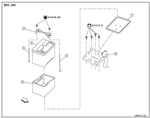
- Battery tray liner
- Battery frame
- Battery
- Battery rod
- Battery cover
- Battery tray
 Front
Front
Removal and Installation (Battery)
REMOVAL
- Pull back cover of battery positive terminal.
- Loosen the battery terminal nuts and disconnect the battery
negative and positive terminals.
CAUTION: To prevent damage to the parts, disconnect the battery negative terminal first.
- Remove battery frame nuts, battery frame and battery rods.
- Remove battery cover and battery.
INSTALLATION
Installation is in the reverse order of removal.
CAUTION:
- Make sure battery tray liner is clean prior to installing new battery.
- To prevent damage to the parts, connect the battery positive terminal first.
- Make sure battery cables are tightly clamped to battery terminals for good contact.
- Check battery terminal for poor connection caused by corrosion.
WARNING: Do not allow battery fluid to come into contact with skin, eyes, fabrics, or painted surfaces. After touching a battery, never touch or rub your eyes until you have thoroughly washed your hands. If acid contacts eyes, skin or clothing, immediately flush with water for 15 minutes and seek medical attention.
Failure to do this may cause personal injury or damage to clothing or the painted surfaces.
Battery terminal nut : 5.0 N┬Ęm (0.51 kg-m, 44 in-lb)
Reset electronic systems as necessary. Refer to .PG-72, "ADDITIONAL SERVICE WHEN REMOVING BATTERY NEGATIVE TERMINAL : Special Repair Requirement"
Removal and Installation (Battery Tray)
REMOVAL
- Remove battery. Refer to PG-75, "Removal and Installation (Battery)".
- Remove air cleaner and air duct. Refer to EM-24, "Removal and Installation".
- Disconnect harness connector from TCM.
- Remove wiring harness retainers.
- Disconnect harness connectors from ECM.
- Remove battery tray. Refer to PG-75, "Exploded View"
- Remove TCM bracket from battery tray (if necessary).
- Remove ECM bracket from battery tray (if necessary).
INSTALLATION
Installation is in the reverse order of removal.
Reset electronic systems as necessary. Refer to PG-72, "ADDITIONAL SERVICE WHEN REMOVING BATTERY NEGATIVE TERMINAL : Special Repair Requirement".

 Battery terminal with fusible link
Exploded View
Cover
Fusible link box (battery)
Positive cable
Battery
Harness connector
Front
Removal and Installation
REMOVAL
Loosen battery terminal n ...
Other materials:
Manual control
While using the Voice Recognition system, it is
possible to select menu options by using the
steering wheel controls instead of speaking voice
commands. To activate manual control mode,
press the PHONE/SEND ( ) button on
the
steering wheel to access the phone menu and
then press either u ...
Three-way catalyst
The three-way catalyst is an emission control
device installed in the exhaust system. Exhaust
gases in the three-way catalyst are burned at
high temperatures to help reduce pollutants.
WARNING
The exhaust gas and the exhaust system
are very hot. Keep people, animals
or f ...
Precaution
Precaution for Supplemental Restraint System (SRS) "AIR BAG" and "SEAT
BELT
PRE-TENSIONER"
The Supplemental Restraint System such as ŌĆ£AIR BAGŌĆØ and ŌĆ£SEAT BELT PRE-TENSIONERŌĆØ,
used along
with a front seat belt, helps to reduce the risk or severity of injury to the
...
