Nissan Rogue Service Manual: Cooling fan
Component Function Check
1.CHECK COOLING FAN FUNCTION
With CONSULT
- Turn ignition switch ON.
- Perform “COOLING FAN (DUAL)” in “ACTIVE TEST” mode of “IPDM E/R” using CONSULT.
- Touch “LOW”, “HI” on the CONSULT screen.
- Check that cooling fan operates.
Is the inspection result normal? YES >> INSPECTION END
NO >> Proceed to EC-458, "Diagnosis Procedure".
Diagnosis Procedure
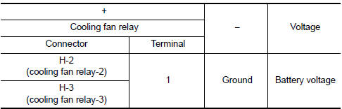
1.CHECK COOLING FAN RELAY POWER SUPPLY CIRCUIT
- Turn ignition switch OFF.
- Disconnect cooling fan relays-2, -3.
- Turn ignition switch ON.
- Check the voltage between cooling fan relays-2, -3 harness connectors and ground.
Is the inspection result normal? YES >> GO TO 2.
NO >> Perform trouble diagnosis for power supply circuit.
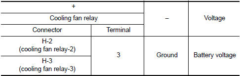
2.CHECK COOLING FAN MOTOR CIRCUIT-1
Check the voltage between cooling fan relays-2, -3 harness connectors and ground.
Is the inspection result normal? YES >> GO TO 3.
NO >> GO TO 4.
3.CHECK COOLING FAN RELAY OUTPUT SIGNAL CIRCUIT
- Turn ignition switch OFF.
- Disconnect IPDM E/R harness connectors.
- Check the continuity between cooling fan relay-2, -3 harness connectors and IPDM E/R harness connector.

- Also check harness for short to ground and to power.
Is the inspection result normal? YES >> GO TO 6.
NO >> Repair or replace error-detected parts.
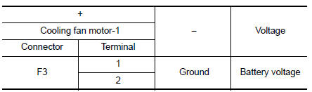
4.CHECK COOLING FAN MOTOR POWER SUPPLY CIRCUIT
- Disconnect cooling fan motor-1 harness connector.
- Check the voltage between cooling fan motor-1 harness connector and ground.
Is the inspection result normal? YES >> GO TO 5.
NO >> Perform trouble diagnosis for power supply circuit.
5.CHECK COOLING FAN MOTOR CIRCUIT-2
- Check the continuity between cooling fan relay-2, -3 harness connectors and cooling fan motor-1, -2 harness connectors.
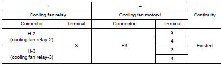
- Also check harness for short to ground and to power.
Is the inspection result normal? YES >> GO TO 11.
NO >> Repair or replace error-detected parts.
6.CHECK COOLING FAN MOTOR CIRCUIT-3
- Check the continuity between IPDM E/R harness connector and cooling fan motor-2 harness connector.
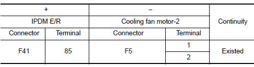
- Also check harness for short to ground and to power.
Is the inspection result normal? YES >> GO TO 7.
NO >> Repair or replace error-detected parts.
7.CHECK COOLING FAN MOTOR CIRCUIT-4
- Check the continuity between cooling fan relay-3 harness connectors and ground.
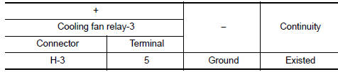
- Also check harness for short to ground and to power.
Is the inspection result normal? YES >> GO TO 8.
NO >> Repair or replace error-detected parts.
8.CHECK COOLING FAN MOTOR CIRCUIT-5
- Check the continuity between cooling fan relay--3 harness connectors and cooling fan motor-2 harness connector.

- Also check harness for short to ground and to power.
Is the inspection result normal? YES >> GO TO 9.
NO >> Repair or replace error-detected parts.
9.CHECK COOLING FAN MOTOR CIRCUIT-4
- Check the continuity between cooling fan motor-2 harness connector and ground.
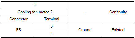
- Also check harness for short to ground and to power.
Is the inspection result normal? YES >> GO TO 10.
NO >> Repair or replace error-detected parts.
10.CHECK COOLING FAN RELAY-2 AND -3
Refer to EC-461, "Component Inspection (Cooling Fan Relay)".
Is the inspection result normal? YES >> GO TO 11.
NO >> Replace malfunctioning cooling fan relay.
11.CHECK COOLING FAN MOTORS-1 AND -2
Refer to EC-461, "Component Inspection (Cooling Fan Motor)".
Is the inspection result normal? YES >> GO TO 12.
NO >> Replace malfunctioning cooling fan motor. Refer to CO-17, "Removal and Installation".
12.CHECK INTERMITTENT INCIDENT
Perform GI-41, "Intermittent Incident".
Is the inspection result normal? YES >> Replace IPDM E/R. Refer to PCS-35, "Removal and Installation".
NO >> Repair or replace error-detected parts.
Component Inspection (Cooling Fan Motor)
1.CHECK COOLING FAN MOTOR
- Turn ignition switch OFF.
- Disconnect cooling fan motor harness connector.
- Supply cooling fan motor terminals with battery voltage and check operation.
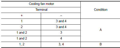
Check that cooling fan speed of condition B is higher than that of A.
Is the inspection result normal? YES >> INSPECTION END
NO >> Replace cooling fan motor. Refer to CO-17, "Removal and Installation".
Component Inspection (Cooling Fan Relay)
1.CHECK COOLING FAN RELAYS
- Turn ignition switch OFF.
- Remove cooling fan relay-2, -3.
- Check the continuity between cooling fan relay-2, -3 terminals as per the following conditions.
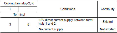
Is the inspection result normal? YES >> INSPECTION END
NO >> Replace cooling fan relay.
 Brake pedal position switch
Component Function Check
1.CHECK BRAKE PEDAL POSITION SWITCH FUNCTION
With CONSULT
Turn ignition switch ON.
Select “BRAKE SW1” in “DATA MONITOR” mode with CONSULT.
...
 Electrical load signal
Description
The electrical load signal (Headlamp switch signal, rear window defogger
switch signal, etc.) is transferred via
the CAN communication.
Component Function Check
1.CHECK REAR WINDOW D ...
Other materials:
Cluster lid C
Exploded View
Audio unit (AUDIO WITHOUT BOSE) /
AV control unit (AUDIO WITH BOSE)
(NAVIGATION WITH BOSE)
A/C switch assembly (AUTOMATIC
AIR CONDITIONING) / front air control
(MANUAL AIR CONDITIONING)
Cluster lid C
Removal and Installation
REMOVAL
Release ...
Panoramic roof glass
Exploded View
Panoramic roof glass
Glass lid
Side trim covers (LH/RH)
Front drain hose (LH/RH)
Moonroof motor assembly
Sunshade motor assembly
Moonroof front bracket (LH/RH)
Moonroof rear bracket (LH/RH)
Rear drain hose (LH/RH)
Moonroof unit assembly
Re ...
U1010 control unit (CAN)
DTC Logic
DTC DETECTION LOGIC
DTC
Display Item
Malfunction Detected Condition
Possible cause
U1010
CONTROL UNIT (CAN)
BCM detected internal CAN communication circuit malfunction.
BCM
Diagnosis Procedure
1.REPLACE BCM
When DTC “U1010” is detected, repla ...
