Nissan Rogue Service Manual: Power generation voltage variable control system operation inspection
Diagnosis Procedure
Regarding Wiring Diagram information. Refer to CHG-7, "Wiring Diagram".
CAUTION: When performing this inspection, always use a charged battery that has completed the battery inspection.
(When the charging rate of the battery is low, the response speed of the voltage change will become slow. This can cause an incorrect inspection.)
1.CHECK ECM (CONSULT)
Perform ECM self-diagnosis with CONSULT. Refer to EC-67, "CONSULT Function".
Self-diagnostic results content No malfunction detected>> GO TO 2.
Malfunction detected>> Check applicable parts, and repair or replace corresponding parts.
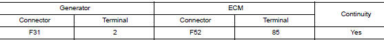
2.CHECK HARNESS BETWEEN GENERATOR AND ECM
- Turn ignition switch OFF.
- Disconnect generator connector and ECM connector.
- Check continuity between generator harness connector and ECM harness connector.
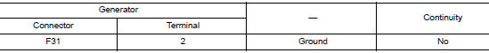
- Check continuity between generator harness connector and ground.
Is the inspection result normal? YES >> Replace ECM. Refer to EC-499, "Removal and Installation".
NO >> Repair harness or connectors between ECM and generator.
 Charging system preliminary inspection
Diagnosis Procedure
1.CHECK BATTERY TERMINALS CONNECTION
Check if battery terminals are clean and tight.
Is the inspection result normal?
YES >> GO TO 2.
NO >> Repair battery term ...
 B terminal circuit
Description
“B” terminal circuit supplies power to charge the battery and to operate the
vehicles electrical system.
Diagnosis Procedure
Regarding Wiring Diagram information. Refer to CHG-7, ...
Other materials:
P0460 fuel level sensor
DTC Description
DTC DETECTION LOGIC
When the vehicle is parked, naturally the fuel level in the fuel tank is
stable. It means that output signal of the
fuel level sensor does not change. If ECM senses sloshing signal from the
sensor, fuel level sensor malfunction
is detected.
DTC No. ...
Inside mirror
Exploded View
MANUAL ANTI-DAZZLING
Windshield glass
Mirror base
Inside mirror
AUTO ANTI-DAZZLING
Windshield glass
Mirror base
Inside mirror
Inside mirror finisher
Harness connector
Bolt
Removal and Installation
MANUAL ANTI-DAZZLING
Removal ...
Moving Object Detection (MOD) (if so equipped)
The MOD system can inform the driver of moving
objects behind the vehicle when backing out of
garages, maneuvering in parking lots and in other
such instances.
The MOD system detects moving objects by
using image processing technology on the image
shown in the display.
The MOD system oper ...
