Nissan Rogue Service Manual: Charging system preliminary inspection
Diagnosis Procedure
1.CHECK BATTERY TERMINALS CONNECTION
Check if battery terminals are clean and tight.
Is the inspection result normal? YES >> GO TO 2.
NO >> Repair battery terminal connection. Confirm repair by performing complete Charging system test using EXP-800 NI or GR8-1200 NI (if available). Refer to the applicable Instruction Manual for proper testing procedures.
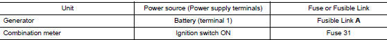
2.CHECK FUSE
Check for blown fuse and fusible link.
Is the inspection result normal? YES >> GO TO 3.
NO >> Replace the blown fuse or fusible link after repairing the affected circuit.
3.CHECK DRIVE BELT TENSION
Check drive belt tension. Refer to MA-13, "DRIVE BELTS : Tension Adjustment".
Is the inspection result normal? YES >> Inspection End.
NO >> Repair as needed.

 Power generation voltage variable control system operation
inspection
Power generation voltage variable control system operation
inspection
Diagnosis Procedure
Regarding Wiring Diagram information. Refer to CHG-7, "Wiring Diagram".
CAUTION:
When performing this inspection, always use a charged battery that has completed
the ...
Other materials:
System description
COMPONENT PARTS
Component Parts Location
View under rear of front passenger
seat
View with spare tire cover removed
Center of back door
View with glove box removed
No.
Component
Function
1
Rod antenna
Refer to AV-232, &quo ...
The low washer fluid warning continues displaying, or
does not display
Description
The warning is still displayed even after washer fluid is added.
The warning is not displayed even though the washer tank is empty.
Diagnosis Procedure
1.CHECK WASHER FLUID LEVEL SWITCH SIGNAL CIRCUIT
Check the washer fluid level switch signal circuit. Refer to MWI-71,
" ...
Precaution
Precaution for supplemental restraint system (srs) "air bag" and "seat
belt
pre-tensioner"
The Supplemental Restraint System such as ŌĆ£AIR BAGŌĆØ and ŌĆ£SEAT BELT
PRE-TENSIONERŌĆØ, used along
with a front seat belt, helps to reduce the risk or severity of injury to the
...
