Nissan Rogue Service Manual: B terminal circuit
Description
“B” terminal circuit supplies power to charge the battery and to operate the vehicles electrical system.
Diagnosis Procedure
Regarding Wiring Diagram information. Refer to CHG-7, "Wiring Diagram".
1.CHECK “B” TERMINAL CONNECTION
- Turn ignition switch OFF.
- Check if “B” terminal is clean and tight.
Is the inspection result normal? YES >> GO TO 2.
NO >> Repair terminal “B” connection. Confirm repair by performing complete Charging system test using the EXP-800 NI or GR8-1200 NI (if available). Refer to applicable Instruction Manual for proper testing procedures.
2.CHECK “B” TERMINAL CIRCUIT
Check voltage between generator “B” terminal and ground.
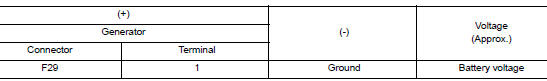
Is the inspection result normal? YES >> GO TO 3.
NO >> Check harness for open between generator and fusible link.
3.CHECK “B” TERMINAL CONNECTION (VOLTAGE DROP TEST)
- Start engine, then engine running at idle and warm.
- Check voltage between battery positive terminal and generator connector “B” terminal.
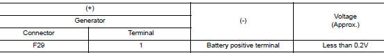
Is the inspection result normal? YES >> “B” terminal circuit is normal. Refer to CHG-11, "Work Flow (With EXP-800 NI or GR8-1200 NI)" or CHG-14, "Work Flow (Without EXP-800 NI or GR8-1200 NI)".
NO >> Check harness between battery and generator for continuity.
 Power generation voltage variable control system operation
inspection
Power generation voltage variable control system operation
inspection
Diagnosis Procedure
Regarding Wiring Diagram information. Refer to CHG-7, "Wiring Diagram".
CAUTION:
When performing this inspection, always use a charged battery that has completed
the ...
 Symptom diagnosis
CHARGING SYSTEM
Symptom Table
...
Other materials:
If your vehicle overheats
WARNING
Do not continue to drive if your vehicle
overheats. Doing so could cause engine
damage or a vehicle fire.
To avoid the danger of being scalded,
never remove the radiator or coolant
reservoir cap while the engine is still
hot. When the radiator o ...
Precaution
Precaution for Supplemental Restraint System (SRS) "AIR BAG" and "SEAT
BELT
PRE-TENSIONER"
The Supplemental Restraint System such as “AIR BAG” and “SEAT BELT PRE-TENSIONER”,
used along
with a front seat belt, helps to reduce the risk or severity of injury to the
...
Power supply and ground circuit
BCM (BODY CONTROL SYSTEM) (WITH INTELLIGENT KEY SYSTEM)
BCM (BODY CONTROL SYSTEM) (WITH INTELLIGENT KEY SYSTEM) : Diagnosis
Procedure
Regarding Wiring Diagram information, refer to BCS-50, "Wiring Diagram".
1. CHECK FUSE
Check that the following fuse is not blown.
Is the fuse blown ...
