Nissan Rogue Service Manual: Harness
Harness Layout
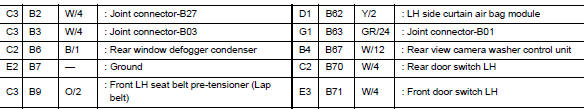
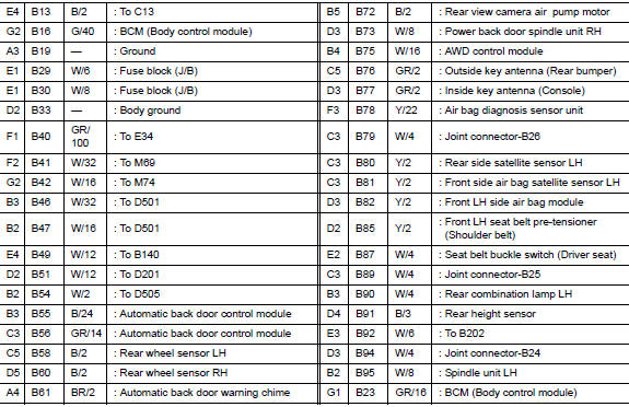
HOW TO READ HARNESS LAYOUT
The following Harness Layouts use a map style grid to help locate connectors on the drawings:
- Main Harness and Main Sub Harness
- Engine Room Harness
- Engine Room Harness (Passenger Compartment)
- Front End Module Harness
- Engine Control Harness
- Body Harness
- Body No. 2 Harness
- Room Lamp Harness
To use the grid reference
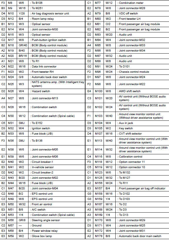
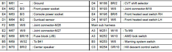
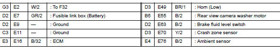
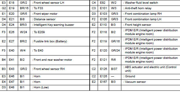
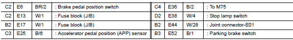
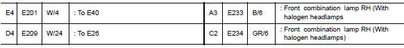
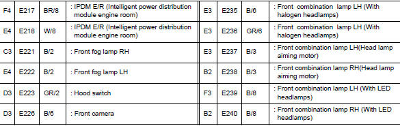
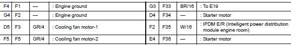
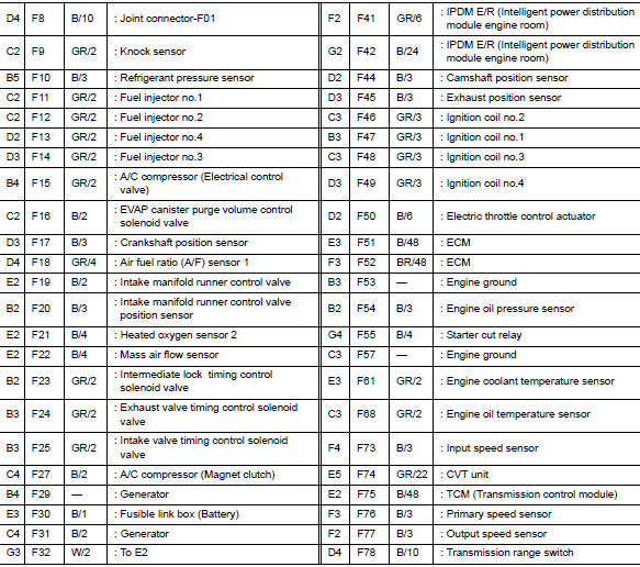
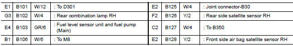
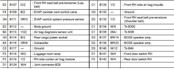
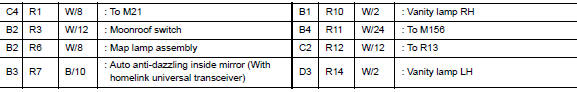
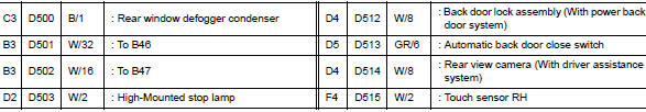
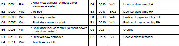
- Find the desired connector number on the connector list.
- Find the grid reference.
- On the drawing, find the crossing of the grid reference letter column and number row.
- Find the connector number in the crossing zone.
- Follow the line (if used) to the connector.
OUTLINE
MAIN HARNESS

ENGINE ROOM HARNESS
ENGINE ROOM HARNESS (PASSENGER COMPARTMENT)

FRONT END MODULE HARNESS
ENGINE CONTROL HARNESS
BODY HARNESS
BODY NO. 2 HARNESS
ROOM LAMP HARNESS

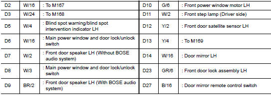
FRONT DOOR LH HARNESS
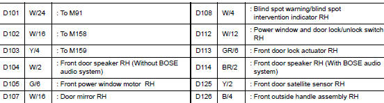
FRONT DOOR RH HARNESS
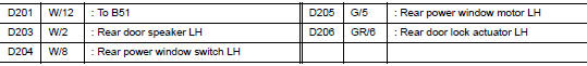
REAR DOOR LH HARNESS
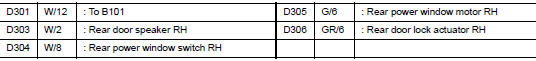
REAR DOOR RH HARNESS
BACK DOOR HARNESS
 Ground
Ground Distribution
MAIN HARNESS
ENGINE ROOM HARNESS
ENGINE CONTROL HARNESS
BODY HARNESS
BODY NO. 2 HARNESS
...
 Electrical units location
Electrical Units Location
ENGINE COMPARTMENT
PASSENGER COMPARTMENT
...
Other materials:
Diagnosis system (BCM) (without intelligent key system)
COMMON ITEM
COMMON ITEM : CONSULT Function (BCM - COMMON ITEM)
APPLICATION ITEM
CONSULT performs the following functions via CAN communication with BCM.
SYSTEM APPLICATION
BCM can perform the following functions.
BUZZER
BUZZER : CONSULT Function (BCM - BUZZER)
DATA MONITOR
ACTIV ...
P0456 EVAP control system
DTC Description
DTC DETECTION LOGIC
This diagnosis detects leaks in the EVAP line between fuel tank and EVAP
canister purge volume control solenoid
valve, using the negative pressure caused by decrease of fuel temperature in the
fuel tank after turning
ignition switch OFF.
If ECM judges t ...
EVAP control system pressure sensor
Exploded View
EVAP control system pressure sensor
O-ring
EVAP canister
EVAP canister vent control valve
EVAP canister vent control valve hose
EVAP vent line
EVAP canister purge hose
Clamp
Front
Removal and Installation
NOTE:
The EVAP canister syst ...
