Nissan Rogue Service Manual: VDC off switch
Component Function Check
1.CHECK VDC OFF SWITCH OPERATION
Check that VDC OFF indicator lamp in combination meter turns ON/OFF when VDC OFF switch is operated.
Is the inspection result normal? YES >> INSPECTION END
NO >> Proceed to BRC-117, "Diagnosis Procedure".
Diagnosis Procedure
1.CHECK VDC OFF SWITCH CIRCUIT
- Turn the ignition switch OFF.
- Disconnect ABS actuator and electric unit (control unit) harness connector.
- Disconnect VDC OFF switch harness connector.
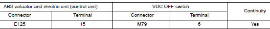
- Check the continuity between ABS actuator and electric unit (control unit) harness connector and VDC OFF switch harness connector.
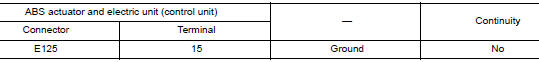
- Check the continuity between ABS actuator and electric unit (control unit) harness connector and ground.
Is the inspection result normal? YES >> GO TO 2.
NO >> Repair or replace error-detected parts.
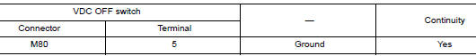
2.CHECK VDC OFF SWITCH GROUND CIRCUIT
Check the continuity between VDC OFF switch harness connector and ground.
the inspection result normal? YES >> GO TO 3.
NO >> Repair or replace error-detected parts.
3.CHECK VDC OFF SWITCH
Check the VDC OFF switch. Refer to BRC-118, "Component Inspection".
Is the inspection result normal? YES >> GO TO 4.
NO >> Replace the VDC OFF switch. Refer to BRC-138, "Removal and Installation".
4.CHECK VDC OFF SWITCH SIGNAL
 With CONSULT
- Connect ABS actuator and electric unit (control unit) harness connector.
- Connect VDC OFF switch harness connector.
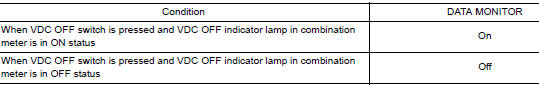
- Select “ABS”, “DATA MONITOR” and “OFF SW” according to this order. Check the VDC OFF switch signal.
Is the inspection result normal? YES >> Inspection End.
NO >> GO TO 5.
5.CHECK TERMINAL
- Check the ABS actuator and electric unit (control unit) pin terminals for damage or loose connection with harness connector.
- Check the VDC OFF switch pin terminals for damage or loose connection with harness connector.
Is the inspection result normal? YES >> Replace the ABS actuator and electric unit (control unit). Refer to BRC-136, "Removal and Installation".
NO >> Repair or replace error-detected parts.
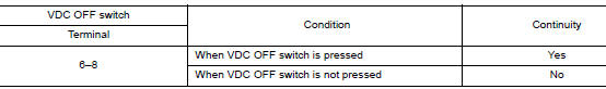
Component Inspection
1.CHECK VDC OFF SWITCH
- Turn the ignition switch OFF.
- Disconnect VDC OFF switch harness connector.
- Check the continuity between terminals of VDC OFF switch connector.
Is the inspection result normal? YES >> Inspection End.
NO >> Replace the VDC OFF switch. Refer to BRC-138, "Removal and Installation".
 Parking brake switch
Component Function Check
1.CHECK PARKING BRAKE SWITCH OPERATION
Check that brake warning lamp in combination meter turns ON/OFF when parking
brake is operated.
Is the inspection result normal?
...
 ABC warning lamp
Component Function Check
1.CHECK ABS WARNING LAMP FUNCTION
Check that ABS warning lamp in combination meter turns ON for 1 second after
ignition switch is turned ON.
CAUTION:
Never start the eng ...
Other materials:
Using the system
Initialization
When the ignition switch is in the ON position,
NISSAN Voice Recognition is initialized, which
takes a few seconds. When completed, the system
is ready to accept voice commands. If
the button is pressed before the
initialization
completes, the system will announce: “Voice
...
Servicing air conditioner
The air conditioner system in your NISSAN vehicle
is charged with a refrigerant designed with
the environment in mind.
This refrigerant does not harm the earth’s
ozone layer.
Special charging equipment and lubricant is required
when servicing your NISSAN air conditioner.
Using improper ...
Wiring diagram
BCM
Wiring Diagram
...
