Nissan Rogue Service Manual: Unit removal and installation
TRANSAXLE ASSEMBLY
Exploded View
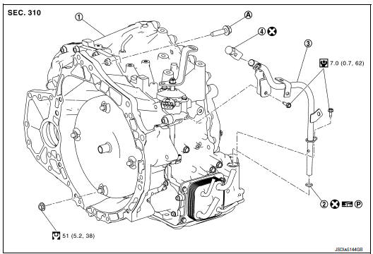
- Transaxle assembly
- O-ring
- CVT fluid charging pipe
- CVT fluid charging pipe cap
- For the tightening torque, refer to TM-220, "Removal and Installation".
 Always replace after every
disassembly.
Always replace after every
disassembly.
 : N·m (kg-m, ft-lb)
 : N·m (kg-m, in-lb)
 : Apply petroleum jelly
Removal and Installation
REMOVAL
WARNING: Do not remove the radiator cap when the engine is hot. Serious burns could occur from high pressure engine coolant escaping from the radiator. Wrap a thick cloth around the cap. Slowly turn it a quarter turn to allow built-up pressure to escape. Carefully remove the cap by turning it all the way.
CAUTION:
- Perform when the engine is cold.
- When replacing the TCM and transaxle assembly as a set, replace the transaxle assembly first and then replace the TCM. Refer to TM-82, "Description".
NOTE: When removing components such as hoses, tubes/lines, etc., cap or plug openings to prevent fluid from spilling.
- Remove engine and transaxle assembly. Refer to EM-81, "Removal and Installation (FWD)" (FWD) or EM-85, "Removal and Installation (AWD)" (AWD).
- Remove the CVT water hoses from engine side. Refer to TM-212, "Removal and Installation".
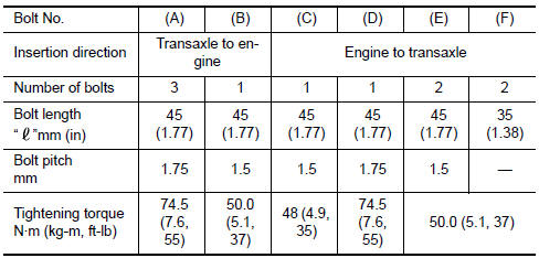
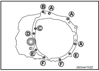
- Remove the transaxle to engine and engine to transaxle bolts.
- Separate the engine from the transaxle and remove the engine from
the front suspension member. Refer
to EM-81, "Removal and Installation (FWD)" (FWD) or EM-85, "Removal and
Installation (AWD)" (AWD).
NOTE: Using paint, put matching marks on the drive plate and torque converter when removing the torque converter to drive plate nuts.
- Remove following parts from transaxle assembly (if necessary).
- Control cable bracket (Refer to TM-197, "Exploded View".)
- Air breather hose (Refer to TM-204, "Exploded View".)
- CVT water hoses and heater thermostat (Refer to TM-217, "Exploded View".)
- Charging pipe and O-ring
INSTALLATION
Installation is in the reverse order of removal.
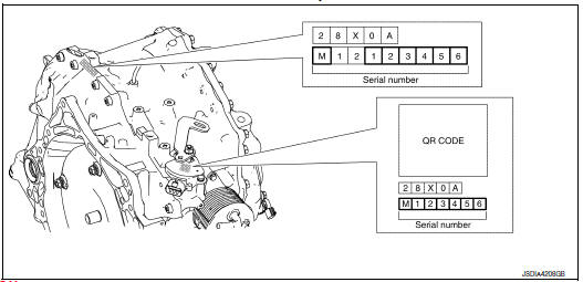
NOTE: Write down the serial number of the new transaxle assembly.
CAUTION:
- When replacing an engine or transaxle you must make sure any dowels are installed correctly during re-assembly
- Improper alignment caused by missing dowels may cause vibration, oil leaks or breakage of drive train components.
- Do not reuse O-rings or copper sealing washers.
- When turning crankshaft, turn it clockwise as viewed from the front of the engine.
- When tightening the nuts for the torque converter while securing the crankshaft pulley bolt, be sure to confirm the tightening torque of the crankshaft pulley bolt. Refer to EM-45, "Removal and Installation".
- After converter is installed to drive plate, rotate crankshaft several turns to check that CVT rotates freely without binding.
- When installing the CVT to the engine, align the matching mark on the drive plate with the matching mark on the torque converter.
- When installing the drive plate to torque converter nuts, tighten them temporarily. then tighten the nuts to the specified torque.
- Install the transaxle assembly and engine assembly mounting bolts according to the following standards.
Inspection and Adjustment
INSPECTION BEFORE INSTALLATION
After inserting a torque converter to the CVT, check dimension (A) with in the reference value limit.
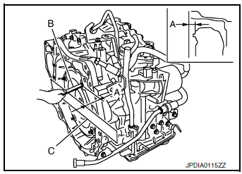
B : Scale
C : Straightedge
Dimension (A) : Refer to TM-226, "Torque Converter".
INSPECTION AFTER INSTALLATION
Check the following items:
- CVT fluid leakage, refer to TM-190, "Inspection".
- For CVT position, refer to TM-196, "Inspection".
- Start the engine and check for coolant leakage from the parts which are removed and reinstalled.
ADJUSTMENT AFTER INSTALLATION
- Adjust the CVT fluid level. Refer to TM-192, "Adjustment".
- Perform "ADDITIONAL SERVICE WHEN REPLACE TRANSAXLE ASSEMBLY". Refer to TM-84, "Description".
 Plug
Plug
Description
Replace the O-ring if oil leakage or exudes from the plug.
Exploded View
Transaxle assembly
O-ring
Plug
: Always replace after every
disassembly.
: N·m (kg-m, ft-lb) ...
 Unit disassembly and assembly
TORQUE CONVERTER AND CONVERTER HOUSING OIL SEAL
Exploded View
Torque converter
O-ring
Converter housing oil seal
Transaxle assembly
: Always replace after every
disassembly.
: A ...
Other materials:
B0092 rear side air bag satellite sensor LH
Description
DTC B0092 REAR SATELLITE SENSOR LH
The rear side air bag satellite sensor LH is wired to the air bag diagnosis
sensor unit. The air bag diagnosis
sensor unit will monitor the rear side air bag satellite sensor LH for internal
failures and its circuits for communication
errors.
P ...
C1770, C1771, C1772, C1773 G sensor
DTC Description
DTC DETECTION LOGIC
DTC
Display Item
Malfunction Detected Condition
Possible Causes
C1770
G SENSOR FL
(G sensor front left)
Malfunction in the G sensor data from front left wheel sensor.
Tire pressure sensor
Tire pressure rece ...
Push-button ignition switch positions
LOCK (Normal parking position):
The ignition switch can only be locked in this
position.
The ignition switch will lock when any door is
opened or closed with the ignition switched off.
ON (Normal operating position):
This position turns on the ignition system and
electrical accessories.
...
