Nissan Rogue Service Manual: Removal and installation
GENERATOR
Exploded View
REMOVAL
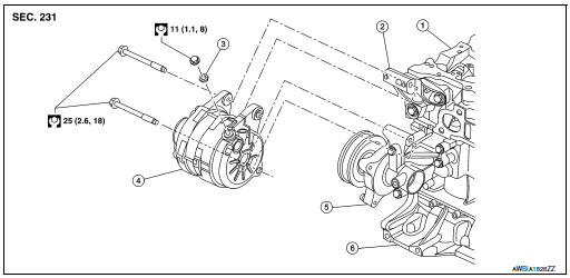
- Cylinder head
- Generator bracket
- Washer
- Generator
- Water pump
- Cylinder block
Removal and Installation
REMOVAL
- Disconnect negative terminal from battery. Refer to PG-75, "Exploded View".
- Remove wheel and tire (RH) using a power tool. Refer to WT-60, "Removal and Installation".
- Remove fender protector side cover. Refer to EXT-28, "FENDER PROTECTOR : Exploded View"
- Remove front air spoiler. Refer to EXT-16, "Exploded View".
- Remove engine under cover. Refer to EXT-37, "ENGINE UNDER COVER : Removal and Installation".
- Remove drive belt. Refer to EM-13, "Removal and Installation".
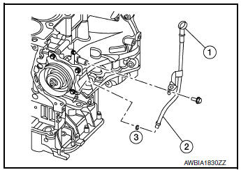
- Remove oil level gauge (1).
- Remove oil level gauge guide (2).
- Remove oil level gauge guide O-ring (3).
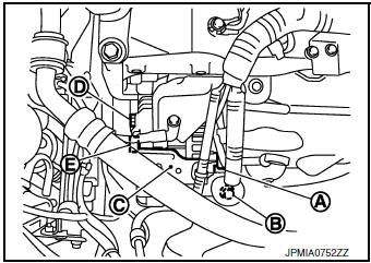
- Disconnect generator connector (A).
- Remove “B” terminal nut (B) and “B” terminal harness.
- Remove harness bracket (C).
NOTE: Harness ground does not have to be removed during bracket removal.
- Remove upper generator mounting bolt (D), using suitable tool.
- Remove lower generator mounting bolt (E), using suitable tool.
- Remove generator upward from the vehicle.
INSTALLATION
Installation is in the reverse order of removal.
- Tighten oil level gauge guide bolt to specification.
Oil level gauge guide bolt : 21.6 N·m (2.2 kg-m, 16 ft-lb)
CAUTION:
- Be careful to tighten “B” terminal nut carefully.
- Install generator and check tension of belt. Refer to EM-13, "Checking".
- Do not reuse oil level gauge guide O-ring.
- Prior to installation, apply clean engine oil to oil level gauge guide O-ring.
- Ensure O-ring sealing surface is free from dust or imprefections.
- Allow engine to run for 5 minutes and inspect for engine oil leaks.
Inspection
GENERATOR PULLEY INSPECTION
Perform the following.
- Make sure that the generator pulley does not bind or rattle.
- Make sure that the generator pulley is tight. Refer to CHG-20, "Exploded View".
 Symptom diagnosis
CHARGING SYSTEM
Symptom Table
...
 Service data and specifications (SDS)
Generator
...
Other materials:
Luggage room lamp
Removal and Installation
REMOVAL
Insert a suitable tool (A) into the gap between the luggage lower
finisher (RH) (2) and the top of luggage room lamp (1) to release
the pawl.
: Pawl
Disconnect the harness connector from the luggage room lamp and remove.
INSTALLATION
Installati ...
Diagnosis system (BCM) (without intelligent key system)
COMMON ITEM
COMMON ITEM : CONSULT Function (BCM - COMMON ITEM)
APPLICATION ITEM
CONSULT performs the following functions via CAN communication with BCM.
Direct Diagnostic Mode
Description
Ecu Identification
The BCM part number is displayed.
Self Diagnostic ...
Cleaning interior
Occasionally remove loose dust from the interior
trim, plastic parts and seats using a vacuum
cleaner or soft bristled brush. Wipe the vinyl and
leather surfaces with a clean, soft cloth dampened
in mild soap solution, then wipe clean with a
dry, soft cloth.
Regular care and cleaning is requ ...
