Nissan Rogue Service Manual: Connector Information
HOW TO USE CONNECTOR INFORMATION
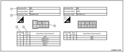
Description
| Number | Item | Description |
| 1 | Connector number |
|
| 2 | Connector type |
|
| 3 | Terminal number |
|
| 4 | Wire color |
|
| B = Black W = White R = Red G = Green L = Blue Y = Yellow LG = Light Green BG = Beige BR = Brown LA = Lavender OR or O = Orange P = Pink PU or V (Violet) = Purple GY or GR = Gray SB = Sky Blue CH = Dark Brown DG = Dark Green |
||
|
||
| 5 | Connector |
|
 Sample/Wiring Diagram -Example-
Each section includes wiring diagrams.
Description
Number
Item
Description
1
Power supply
This means the power supply of fusible link or fuse.
...
 Abbreviations
Abbreviation List
The following ABBREVIATIONS are used:
...
Other materials:
How to erase permanent DTC
Description
OUTLINE
When a DTC is stored in ECM
When a DTC is stored in ECM and MIL is ON, a permanent DTC is erased with MIL
shutoff if the same malfunction
is not detected after performing the driving pattern for MIL shutoff three times
in a raw.
*1: When the same malfunction is detecte ...
P0171 fuel injection system function
DTC Description
DTC DETECTION LOGIC
With the Air/Fuel Mixture Ratio Self-Learning Control, the actual mixture
ratio can be brought closely to the
theoretical mixture ratio based on the mixture ratio feedback signal from the
A/F sensors 1. The ECM calculates
the necessary compensation to corr ...
Unit disassembly and assembly
FRONT DRIVE SHAFT
Exploded View (LH)
Shaft
Circular clip
Dust shield
Housing
Snap ring
Spider assembly
Stopper ring
Boot
Boot band
Joint sub-assembly
Wheel side
Disassembly and Assembly (LH)
DISASSEMBLY
Transaxle Assembly Side
Fix shaft with a v ...
