Nissan Rogue Owners Manual: Push-Button Ignition Switch (if so equipped)
| WARNING Do not operate the push-button ignition switch while driving the vehicle except in an emergency. (The engine will stop when the ignition switch is pushed 3 consecutive times in quick succession or the ignition switch is pushed and held for more than 2 seconds.) If the engine stops while the vehicle is being driven, this could lead to a crash and serious injury. |
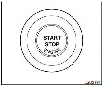
Push-Button Ignition Switch (if so equipped)
When the ignition switch is pushed without depressing the brake pedal, the ignition switch will illuminate.
Push the ignition switch center:
- once to change to ON.
- two times to change to OFF.
The ignition switch will automatically return to the LOCK position when any door is either opened or closed with the switch in the OFF position.
The ignition lock is designed so that the ignition switch position cannot be switched to OFF until the shift lever is moved to the P (Park) position.
When the ignition switch cannot be pushed toward the OFF position, proceed as follows:
- Move the shift lever into the P (Park) position.
- Push the ignition switch. The ignition switch position will change to the ON position.
- Push the ignition switch again to the OFF position.
The shift lever can be moved from the P (Park) position if the ignition switch is in the ON position and the brake pedal is depressed.
If the battery of the vehicle is discharged, the push-button ignition switch cannot be moved from the LOCK position.
Some indicators and warnings for operation are displayed on the vehicle information display. For additional information, refer to “Vehicle information display” in the “Instruments and controls” section of this manual.
- Operating range
- Push-button ignition switch positions
- NISSAN Intelligent Key® battery discharge (if so equipped)
- NISSAN vehicle immobilizer system
 Ignition switch (if so equipped)
WARNING
Never remove or turn the key to the
LOCK position while driving. The steering
wheel will lock (for models with a
steering lock mechanism). This may
cause the d ...
 Operating range
Operating range
The Intelligent Key functions can only be used
when the Intelligent Key is within the specified
operating range.
When the Intelligent Key battery is almost discharged
or str ...
Other materials:
Center console assembly
Exploded View
Center console cup holder (without
heated seats)
Coin tray insert
Center console cup holder (with
heated seats)
Front heated seat switch (RH)
Front heated seat switch (LH)
Shift selector finisher
Shift selector finisher mat
Center console side ...
Shift position indicator circuit
Component Parts Function Inspection
1.CHECK SHIFT POSITION INDICATOR
Start the engine.
Shift selector lever.
Check that the selector lever position and the shift position
indicator on the combination meter are identical.
Is the inspection result normal?
YES >> ...
Front disc brake
Brake Burnishing
CAUTION:
Burnish contact surfaces between brake pads and disc brake
rotor according to the following procedure
after refinishing the disc brake rotor, replacing brake pads or if a soft
pedal occurs at very low
mileage.
Be careful of vehicle speed. Brakes ...
