Nissan Rogue Service Manual: Moonroof motor assembly
Exploded View
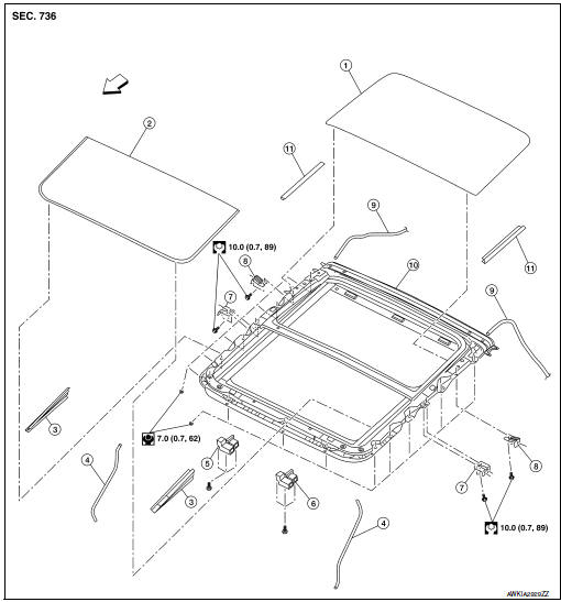
- Panoramic roof glass
- Glass lid
- Side trim covers (LH/RH)
- Front drain hose front (LH/RH)
- Moonroof motor assembly
- Sunshade motor assembly
- Moonroof front bracket (LH/RH)
- Moonroof rear bracket (LH/RH)
- Drain hose rear (LH/RH)
- Moonroof unit assembly
- Rear trim (LH/RH)
 Front
Front
Removal and Installation
REMOVAL
- Close glass lid.
- Remove the headlining. Refer to INT-30, "Removal and Installation".
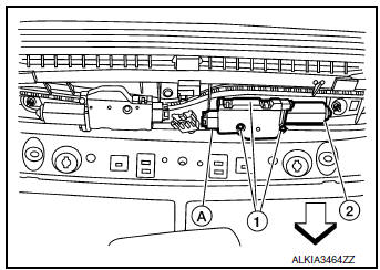
- Remove moonroof motor assembly screws (1).Front
- Disconnect harness connector (A) and remove moonroof motor
assembly (2) from moonroof unit assembly front end rail.
CAUTION: Do not run the removed moonroof motor assembly as a single unit.
INSTALLATION
- Move moonroof motor assembly laterally little by little so that the
gear is completely engaged into the wire
on the moonroof unit assembly, and the mounting surfaces become parallel.
Install the moonroof motor
assembly screws and tighten.
CAUTION: Before installing the motor, be sure to place the link and wire assembly in the symmetrical and fully closed position.
NOTE: If necessary, insert a suitable tool into the drive key and rotate right or left slightly to assist in complete moonroof motor gear alignment.
- Remainder of installation is in the reverse order of removal.
- Synchronize moonroof motor assembly with moonroof unit assembly. Refer to RF-24, "ADDITIONAL SERVICE WHEN REPLACING CONTROL UNIT : Special Repair Requirement".
 Panoramic roof glass
Exploded View
Panoramic roof glass
Glass lid
Side trim covers (LH/RH)
Front drain hose (LH/RH)
Moonroof motor assembly
Sunshade motor assembly
Moonroof front bracke ...
 Moonroof unit assembly
Inspection
WIND DEFLECTOR
Open glass lid fully.
Visually check for proper installation, damaged/deteriorated components,
or foreign objects within mechanism.
Correct as required for smooth ...
Other materials:
Periodic maintenance
IN-CABIN MICROFILTER
Removal and Installation
REMOVAL
Release the tab and remove the in-cabin microfilter cover (1)
from under the RH side of the instrument panel.
CAUTION:
Use care when lifting up on the tab to avoid damaging it.
Remove the in-cabin microfilter (2).
CAUT ...
C1730, C1731, C1732, C1733 flat tire
DTC Logic
NOTE:
The Signal Tech II Tool [- (J-50190)] can be used to perform the following
functions. Refer to the Signal Tech II
User Guide for additional information.
Activate and display TPMS sensor IDs
Display tire pressure reported by the TPMS sensor
Read TPMS DTC ...
Preparation
Special Service Tool
The actual shape of the tools may differ from those illustrated here.
Tool number
(TechMate No.)
Tool name
Description
—
(J-46532)
Brake height tool
Measuring brake pedal height
38-PFM92
( — )
ProCut™ PFM Serie ...
