Nissan Rogue Owners Manual: Heater and Air Conditioner (automatic) (if so equipped)
Heater and Air Conditioner
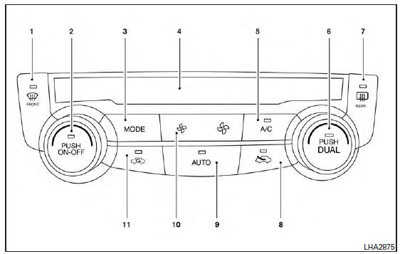
 (front defroster) button
- Temperature control dial (driver’s side) / ON-OFF button
- MODE (manual air flow control) button
- Display screen
- A/C (air conditioner) button
- Temperature control dial (passenger’s side)/DUAL (passenger’s side temperature control) button
-
 (rear window and
outside mirror
(if so equipped) defroster) button
(rear window and
outside mirror
(if so equipped) defroster) button -
 Fresh air intake
button
Fresh air intake
button - AUTO (automatic mode) button
-
 (fan speed control)
buttons
(fan speed control)
buttons -
 Air recirculation
button
Air recirculation
button
WARNING
|
NOTE:
- Odors from inside and outside the vehicle can build up in the air conditioner unit. Odor can enter the passenger compartment through the vents.
- When parking, set the heater and air conditioner
controls to turn off air recirculation to
allow fresh air into the passenger compartment.
This should help reduce odors inside the vehicle.
 Air flow charts
The following charts show the button and dial
positions for MAXIMUM AND QUICK heating,
cooling or defrosting. The air recirculation indicator
should always be in the OFF position
for heating and d ...
 Automatic operation
Cooling and/or dehumidified heating
(AUTO)
This mode may be used all year round as the
system automatically works to keep a constant
temperature. Air flow distribution and fan speed
are also cont ...
Other materials:
Text messaging
WARNING
Laws in some jurisdictions may restrict
the use of “Text-to-Speech.” Check local
regulations before using the feature.
Laws in some jurisdictions may restrict
the use of some of the applications and
features, such as social networking and
te ...
System
EPS SYSTEM
EPS SYSTEM : System Description
SYSTEM DIAGRAM
INPUT/OUTPUT SIGNAL
Communicates the signal from each control unit via CAN communication.
Control unit
Signal status
ECM
Transmits the following signal to EPS control unit via CAN
communica ...
Starting the engine (models without NISSAN
Intelligent Key® system)
Apply the parking brake.
Move the shift lever to P (Park) or N (Neutral).
P (Park) is recommended.
The shift lever cannot be moved out of
P (Park) and into any of the other gear
positions if the ignition key is turned to
the OFF position or if the key is removed
from the ignition ...
