Nissan Rogue Service Manual: DTC/circuit diagnosis
U1000 CAN COMM CIRCUIT
Description
Refer to LAN-8, "System Description".
DTC Logic
DTC DETECTION LOGIC
|
CONSULT Display |
DTC Detection Condition |
Possible Cause |
| CAN COMM CIRCUIT [U1000] | When IPDM E/R cannot communicate with CAN communication signal continuously for 2 seconds or more. | In CAN communication system, any item (or items) of
the following listed below is malfunctioning:
|
Diagnosis Procedure
1. PERFORM SELF DIAGNOSTIC RESULT
- Turn ignition switch ON and wait for 2 second or more.
- Check “SELF-DIAG RESULTS” of “IPDM E/R”.
Is “CAN COMM CIRCUIT” displayed? YES >> Refer to LAN-17, "Trouble Diagnosis Flow Chart".
NO >> Refer to GI-41, "Intermittent Incident".
B120E IPDM E/R
DTC Logic
DTC DETECTION LOGIC
|
CONSULT Display |
DTC Detection Condition |
Possible Cause |
| USM ECU Not configured [B120E] | The IPDM E/R detects 0V for greater than 2 seconds.
ECU internal failure. |
IPDM E/R |
DTC CONFIRMATION PROCEDURE
1.PERFORM DTC CONFIRMATION
- Turn ignition switch ON.
- Turn ignition switch OFF and wait 1 second or more.
- Turn ignition switch ON.
- Perform “Self Diagnostic Result” of “IPDM E/R” using CONSULT.
Is DTC B120E displayed? YES >> Refer to PCS-32, "Diagnosis Procedure".
NO >> Inspection End.
Diagnosis Procedure
1. PERFORM SELF DIAGNOSTIC RESULT
Perform “Self Diagnostic Result” of “IPDM E/R” using CONSULT.
Is display history of DTC B120E CRNT? YES >> Replace IPDM E/R. Refer to PCS-35, "Removal and Installation".
NO >> Refer to GI-41, "Intermittent Incident".
B20DD IGNITION RELAY ON CIRCUIT
DTC Logic
DTC DETECTION LOGIC
|
CONSULT Display |
DTC Detection Condition |
Possible Cause |
| IGN RELAY ON [B20DD] | The ignition relay ON is detected for 1 second at ignition switch OFF (CPU monitors the status at the contact and excitation coil circuits of the ignition relay inside it | IPDM E/R |
DTC CONFIRMATION PROCEDURE
1.PERFORM DTC CONFIRMATION
- Turn ignition switch ON.
- Turn ignition switch OFF and wait 1 second or more.
- Turn ignition switch ON.
- Perform “Self Diagnostic Result” of “IPDM E/R” using CONSULT.
Is DTC B20DD displayed? YES >> Refer to PCS-32, "Diagnosis Procedure".
NO >> Inspection End.
Diagnosis Procedure
1. PERFORM SELF DIAGNOSTIC RESULT
Perform “Self Diagnostic Result” of “IPDM E/R” using CONSULT.
Is display history of DTC B20DD CRNT? YES >> Replace IPDM E/R. Refer to PCS-35, "Removal and Installation".
NO >> Refer to GI-41, "Intermittent Incident".
B20DE IGNITION RELAY OFF CIRCUIT
DTC Logic
DTC DETECTION LOGIC
|
CONSULT Display |
DTC Detection Condition |
Possible Cause |
| IGN RELAY OFF [B20DE] | The ignition relay OFF is detected for 1 second at ignition switch ON (CPU monitors the status at the contact and excitation coil circuits of the ignition relay inside it). | IPDM E/R |
DTC CONFIRMATION PROCEDURE
1.PERFORM DTC CONFIRMATION
- Turn ignition switch ON.
- Turn ignition switch OFF and wait 1 second or more.
- Turn ignition switch ON.
- Perform “Self Diagnostic Result” of “IPDM E/R” using CONSULT.
Is DTC B20DE displayed? YES >> Refer to PCS-33, "Diagnosis Procedure".
NO >> Inspection End.
Diagnosis Procedure
1. PERFORM SELF DIAGNOSTIC RESULT
Perform “Self Diagnostic Result” of “IPDM E/R” using CONSULT.
Is display history of DTC B20DE CRNT? YES >> Replace IPDM E/R. Refer to PCS-35, "Removal and Installation".
NO >> Refer to GI-41, "Intermittent Incident".
POWER SUPPLY AND GROUND CIRCUIT
Diagnosis Procedure
Regarding Wiring Diagram information, refer to PCS-24, "Wiring Diagram".
1. CHECK FUSE AND FUSIBLE LINKS
Check that the following IPDM E/R fuse or fusible links are not blown.
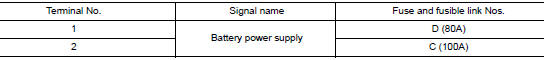
Is the fuse blown? YES >> Replace the blown fuse or fusible link after repairing the affected circuit.
NO >> GO TO 2.
2. CHECK BATTERY POWER SUPPLY CIRCUIT
- Disconnect IPDM E/R connector E118.
- Check voltage between IPDM E/R connector E118 and ground.
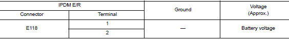
Is the inspection result normal? YES >> GO TO 3.
NO >> Repair or replace harness or connectors.
3. CHECK GROUND CIRCUIT
- Disconnect IPDM E/R connectors E119, E120 and E121.
- Check continuity between IPDM E/R connectors and ground.
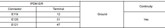
Is the inspection result normal? YES >> Inspection End.
NO >> Repair or replace harness or connectors.
 Wiring diagram
IPDM E/R (INTELLIGENT POWER DISTRIBUTION MODULE ENGINE
ROOM)
Wiring Diagram
...
 Removal and installation
IPDM E/R (INTELLIGENT POWER DISTRIBUTION MODULE ENGINE
ROOM)
Exploded View
IPDM E/R cover
IPDM E/R
IPDM E/R case
IPDM E/R harness cover A
IPDM E/R harness cover B
Front
Remo ...
Other materials:
Removal and installation
A/C SWITCH ASSEMBLY
Removal and Installation
REMOVAL
Release the A/C switch assembly clips and pawls using a suitable
tool.
: Metal clip
: Pawl
Disconnect the harness connector from the A/C switch assembly
(1) and remove.
INSTALLATION
Installation is in the reve ...
Parking brake front cable
Removal and Installation
REMOVAL
Remove the instrument lower panel LH. Refer to IP-22, "Removal and
Installation".
Remove driver seat (LH). Refer to SE-32, "DRIVER SIDE : Removal
and Installation"
Remove the center console. Refer to IP-18, "R ...
Preparation
Special Service Tool
The actual shape of the tools may differ from those illustrated here.
Tool number
(TechMate No.)
Tool name
Description
—
(J-46532)
Brake height tool
Measuring brake pedal height
38-PFM92
( — )
ProCut™ PFM Serie ...
