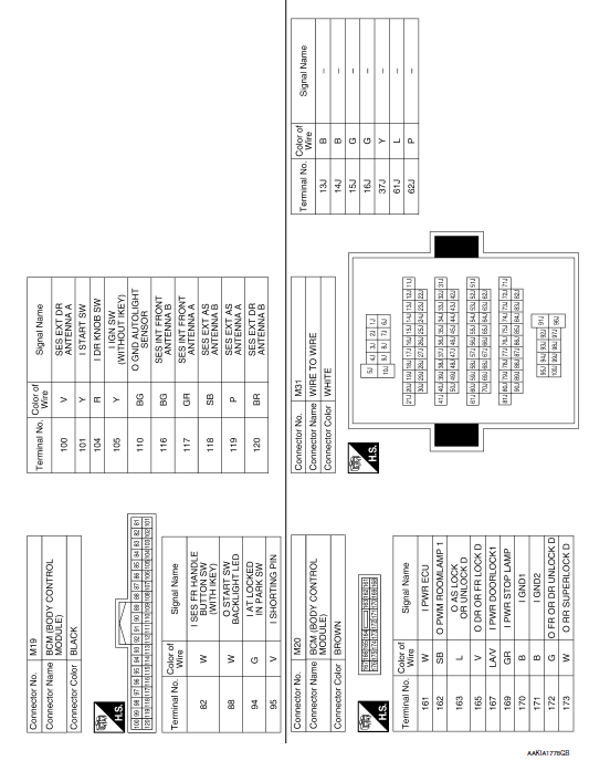
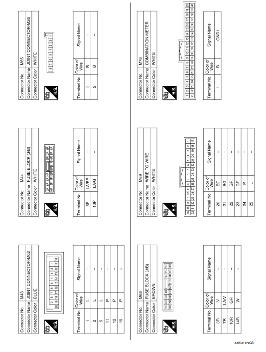
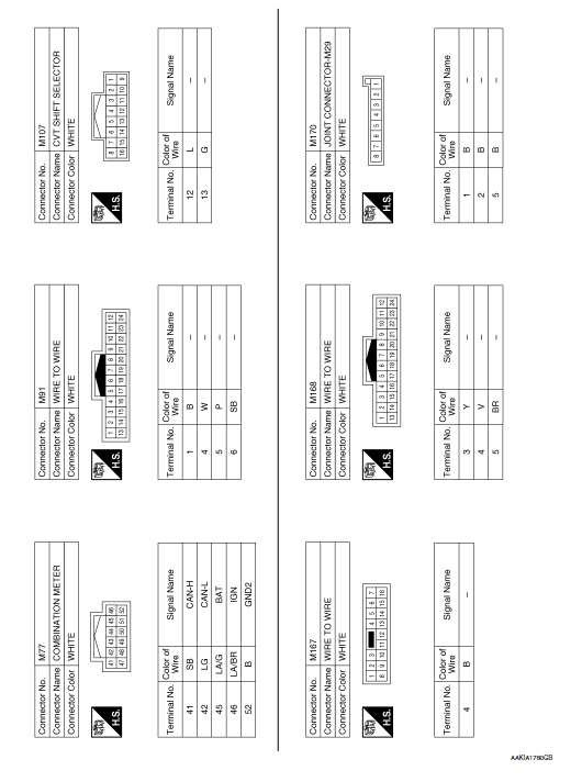
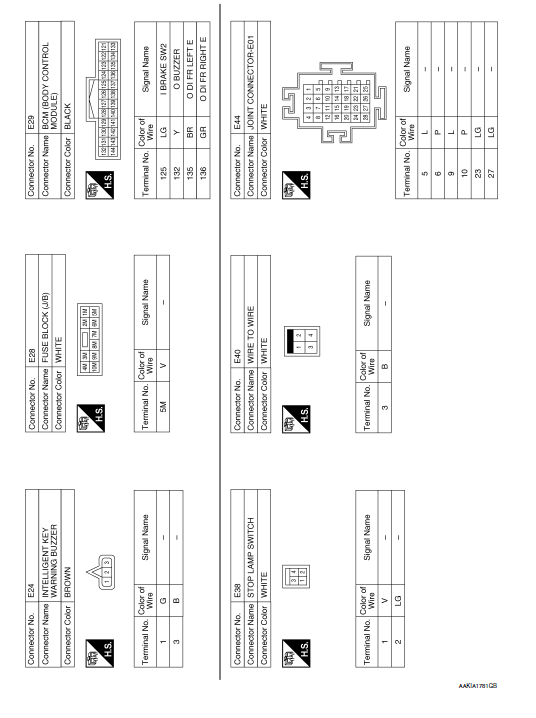
Nissan Rogue Service Manual: Wiring diagram
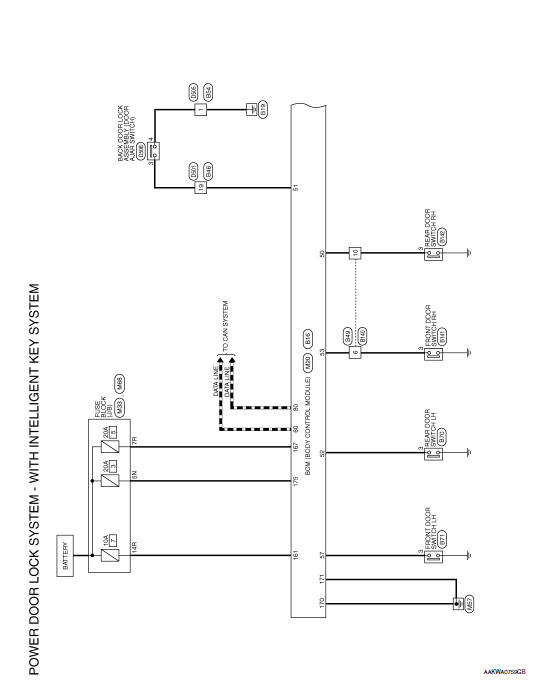
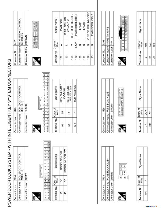
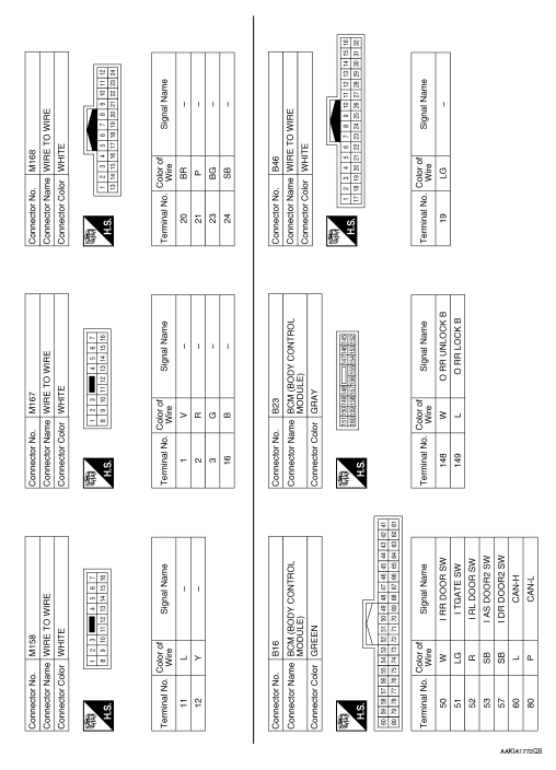
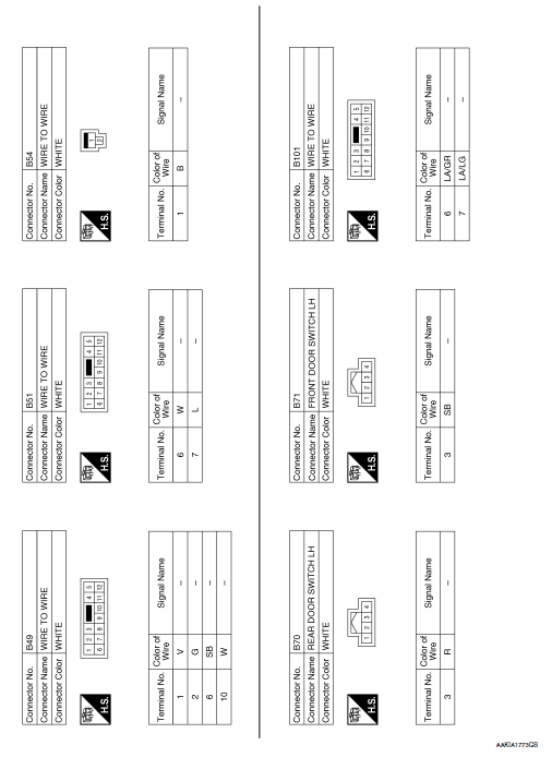
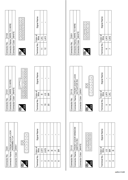
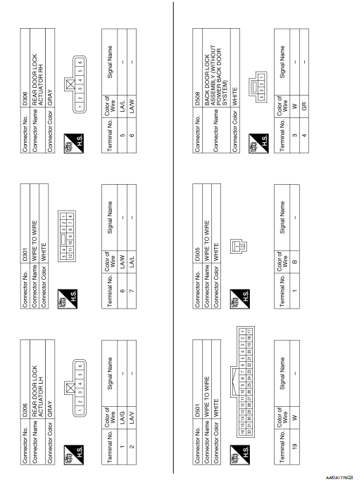
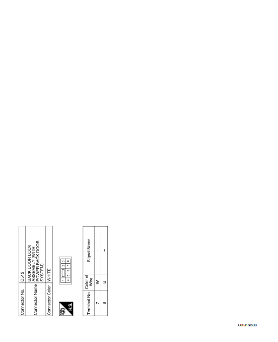
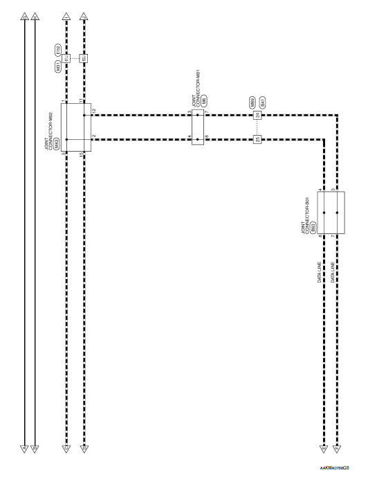
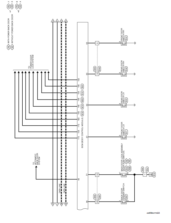
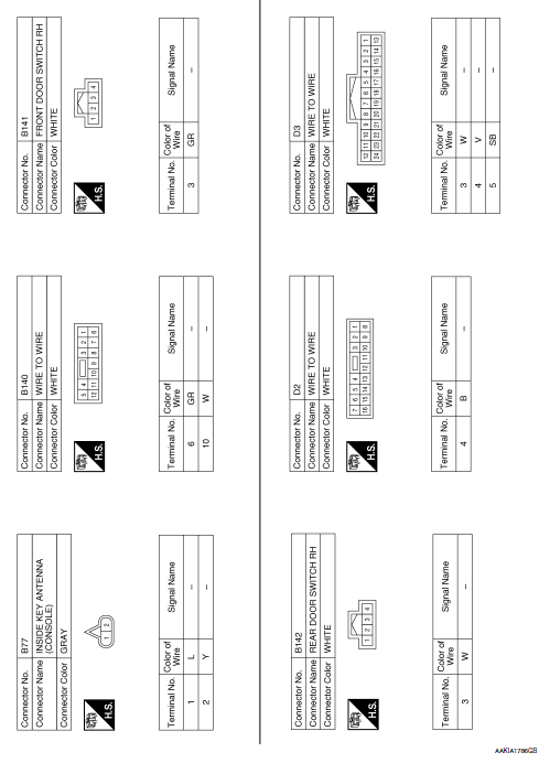
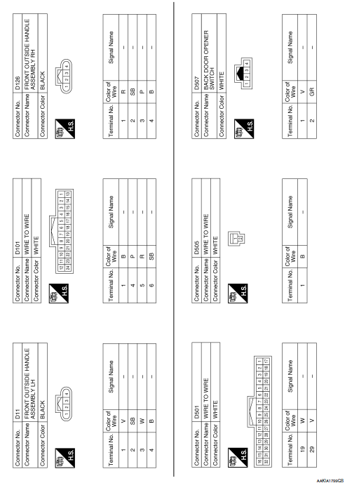
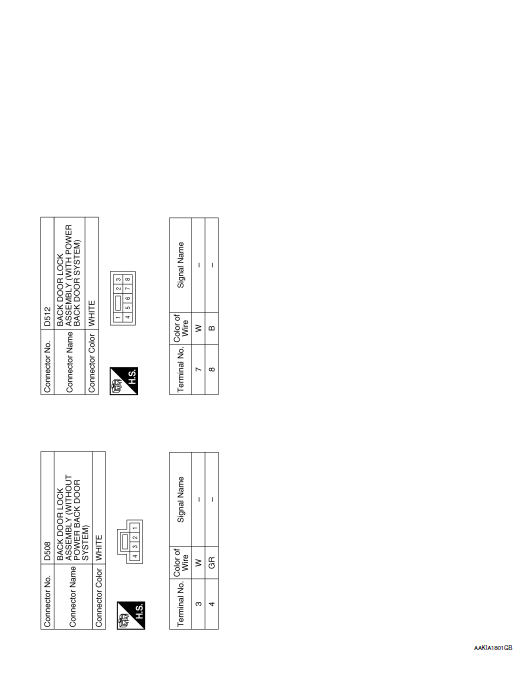
POWER DOOR LOCK SYSTEM
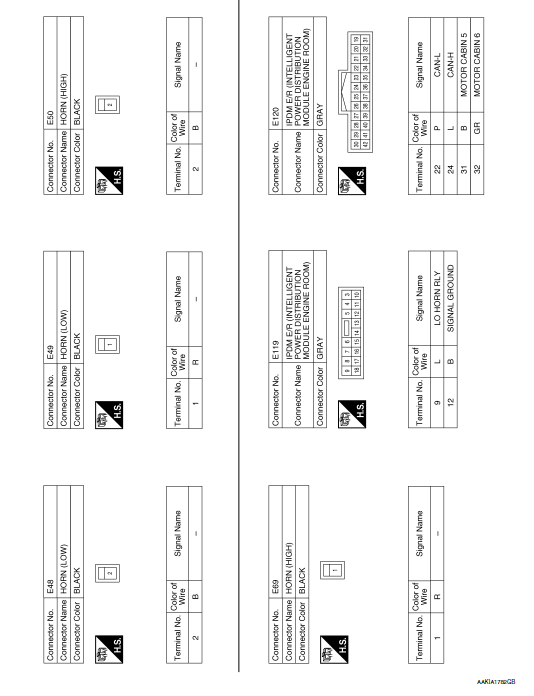
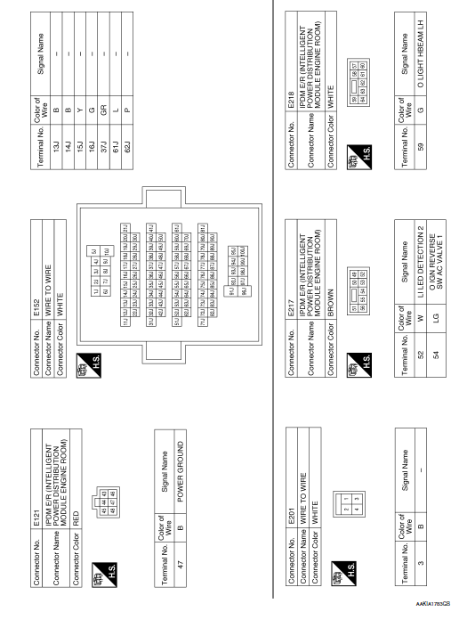
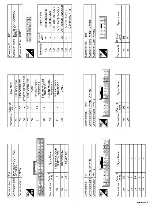
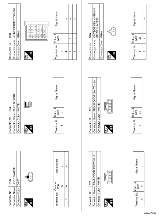
Wiring Diagram


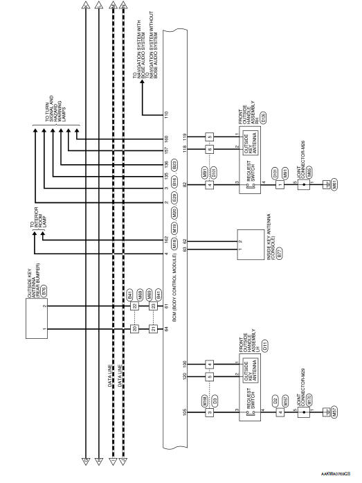
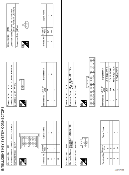
INTELLIGENT KEY SYSTEM
Wiring Diagram

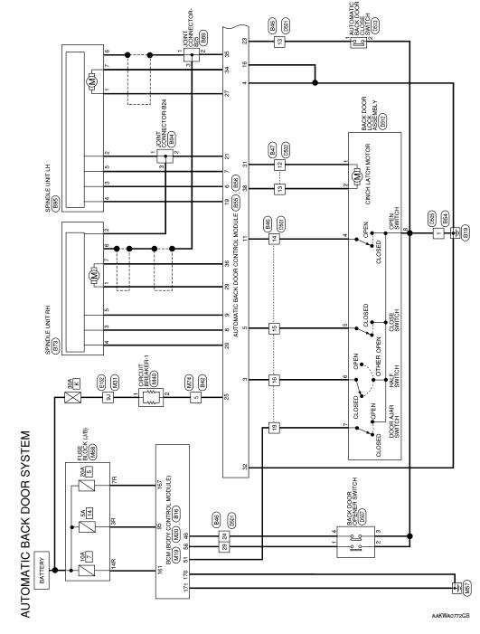
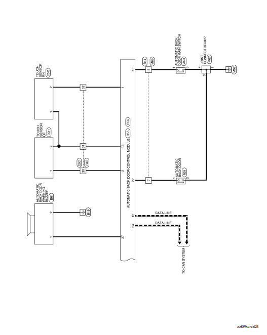
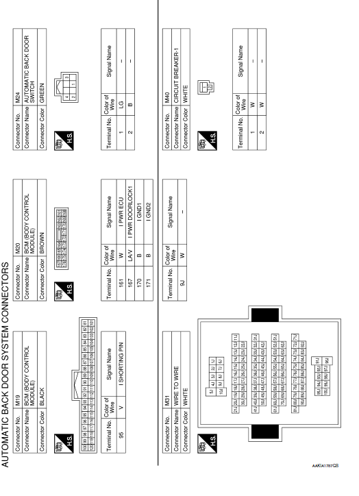
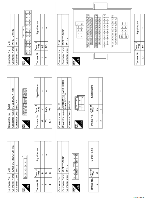
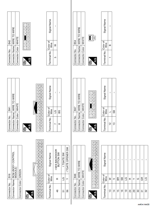
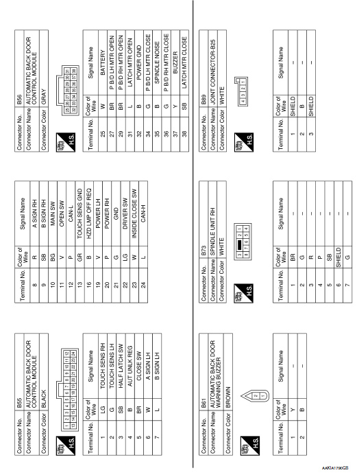
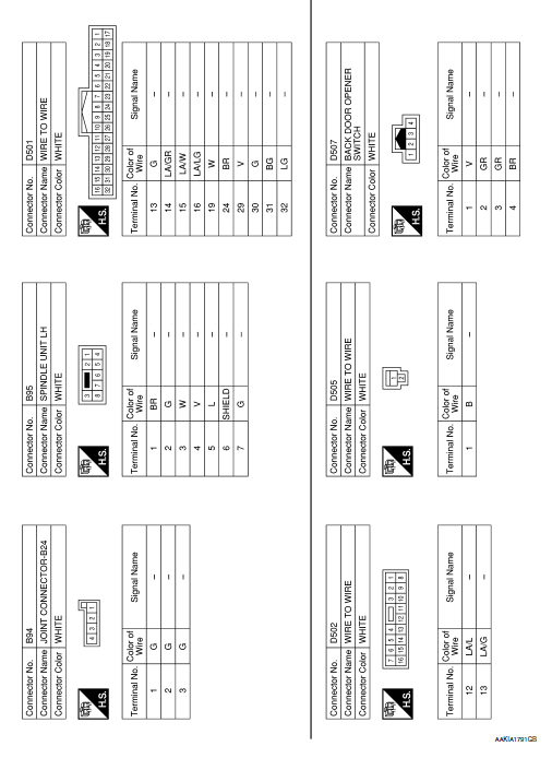
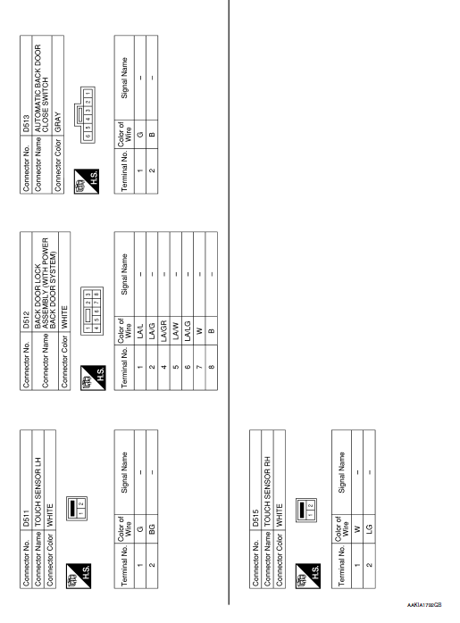
AUTOMATIC BACK DOOR SYSTEM
Wiring Diagram
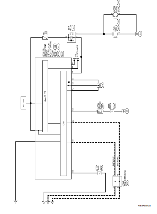
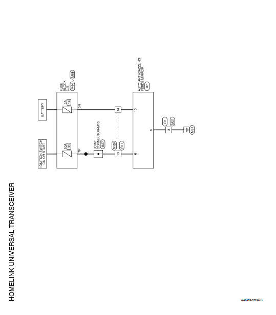
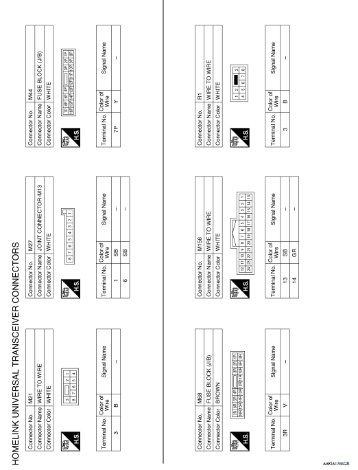
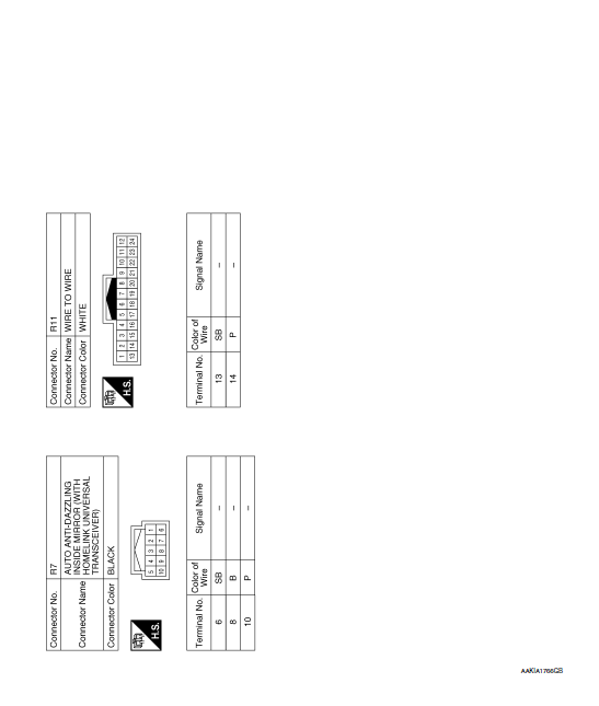
HOMELINK UNIVERSAL TRANSCEIVER
Wiring Diagram
 ECU diagnosis information
AUTOMATIC BACK DOOR CONTROL UNIT
Reference Value
VALUES ON THE DIAGNOSIS TOOL
CONSULT MONITOR ITEM
TERMINAL LAYOUT
PHYSICAL VALUES
Fail Safe
DTC Inspection Prior ...
 Basic inspection
DIAGNOSIS AND REPAIR WORK FLOW
Work Flow
OVERALL SEQUENCE
DETAILED FLOW
1.GET INFORMATION FOR SYMPTOM
Get detailed information from the customer about the symptom (the
condition a ...
Other materials:
Service data and specifications (SDS)
Wheel Alignment (Unladen*1)
*1: Fuel, engine coolant, and lubricants are full. Spare tire, jack, hand
tools, and mats are in designated positions.
*2: Since an adjustment mechanism is not included, the value of the left and
right wheels must be used as the standard value.
Wheelarch Height ...
P0462, P0463 fuel level sensor
DTC Description
DTC DETECTION LOGIC
This diagnosis indicates the former, to detect open or short circuit
malfunction.
DTC No.
CONSULT screen terms
(Trouble diagnosis content)
DTC detecting condition
P0462
FUEL LEVL SEN/CIRC
(Fuel level sensor ″A″ circu ...
Daytime running light system
The daytime running lights automatically illuminate
when the engine is started with the parking
brake released. The daytime running lights operate
with the headlight switch in the OFF position
or in the position. Turn the
headlight switch
to the position for full
illumination when
drivin ...
