Nissan Rogue Service Manual: Removal and installation
IPDM E/R (INTELLIGENT POWER DISTRIBUTION MODULE ENGINE ROOM)
Exploded View
- IPDM E/R cover
- IPDM E/R
- IPDM E/R case
- IPDM E/R harness cover A
- IPDM E/R harness cover B
 Front
Front
Removal and Installation
CAUTION: IPDM E/R integrated relays are not serviceable parts, do not remove from the IPDM E/R.
REMOVAL
- Disconnect the negative battery terminal. Refer to PG-75, "Removal and Installation (Battery)".
- Remove air duct (inlet). Refer to EM-24, "Exploded View".
- Release pawls on IPDM E/R cover (1) and remove.
 : Pawls
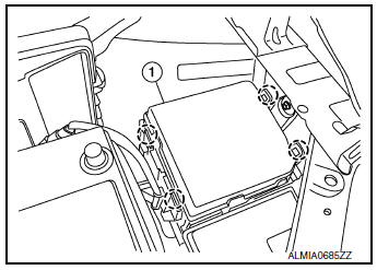
- Release pawls and remove IPDM E/R (1) from the IPDM E/R
case (2).
 : Pawls
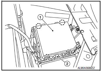
- Disconnect the harness connectors from IPDM E/R (1).
CAUTION: Replace the IPDM E/R if it has been dropped or sustained an impact.

- Release the negative battery cable and harness clips from the IPDM E/R case.
- Release the pawls on the IPDM/ E/R harness covers A, B and remove from the IPDM E/R case.
- Remove the bolts from the IPDM E/R case.
- Remove the bolt (A) from the fusible link box (battery).

- Release the pawls on the fusible link box (battery) case (2) and
remove from the IPDM E/R case (1).: Pawls

INSTALLATION
Installation is in the reverse order of removal.
 DTC/circuit diagnosis
U1000 CAN COMM CIRCUIT
Description
Refer to LAN-8, "System Description".
DTC Logic
DTC DETECTION LOGIC
CONSULT Display
DTC Detection Condition
Possible Cause
...

Other materials:
C1729 vehicle speed signal
DTC Logic
NOTE:
The Signal Tech II Tool [- (J-50190)] can be used to perform the following
functions. Refer to the Signal Tech II
User Guide for additional information.
Activate and display TPMS sensor IDs
Display tire pressure reported by the TPMS sensor
Read TPMS DTC ...
How to check terminal
CONNECTOR AND TERMINAL PIN KIT
Use the connector and terminal pin kits listed below when
replacing connectors or terminals.
The connector and terminal pin kits contain some of the most
commonly used NISSAN/INFINITI connectors
and terminals. For detailed connector and termin ...
Exhaust gas (carbon monoxide)
WARNING
Do not breathe exhaust gases; they
contain colorless and odorless carbon
monoxide. Carbon monoxide is dangerous.
It can cause unconsciousness or
death.
If you suspect that exhaust fumes are
entering the vehicle, drive with all windows
fully ...
