Nissan Rogue Service Manual: Cowl top
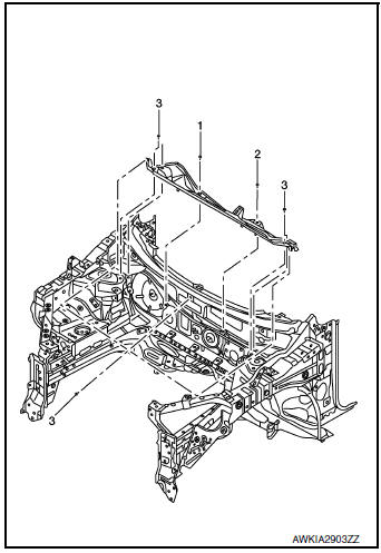
Exploded View
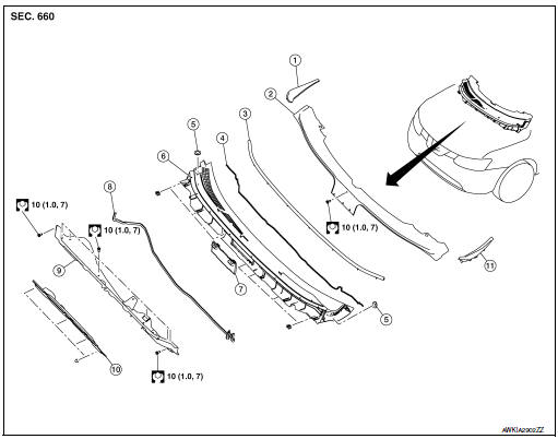
- Cowl top side trim cover (RH)
- Cowl top cover screen
- Cowl top cover seal
- EPT seal
- Cowl top cover plug
- Cowl top cover
- Cowl top cover mask
- Cowl top extension seal
- Cowl top extension
- Cowl top insulation
- Cowl top side trim cover (LH)
Removal and Installation
COWL TOP COVER
Removal
- Remove front wiper arms (LH/RH). Refer to WW-63, "Removal and Installation".
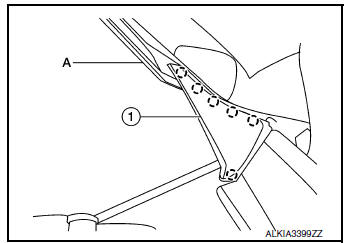
- Release pawls using suitable tool (A) and remove cowl top side
trim cover (1) (LH/RH).
 : Pawl
- Disconnect front washer tube connector.
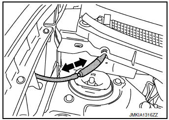
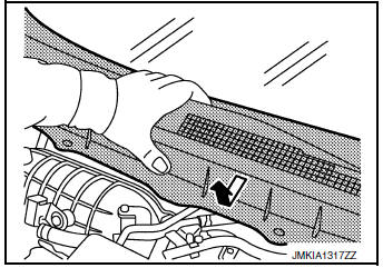
- Remove cowl top cover clips, then pull forward to release cowl top cover and remove.
CAUTION: When performing the procedure after removing cowl top cover, cover the lower end of windshield glass with urethane etc.
- Remove the following parts after removing cowl top cover (if necessary).
- Cowl top seal
- Cowl top cover plug
- Washer nozzle, Refer to WW-60, "Removal and Installation - Front Washer Nozzle".
- Washer tube,WW-60, "Removal and Installation - Front Washer Nozzle".
- EPT sealer
Installation
Installation is in the reverse order of removal.
CAUTION: When installing cowl top cover, check that clips are securely fitted in body panel holes and then press them in.
COWL TOP EXTENSION
Removal
- Remove the front wiper drive assembly. Refer to WW-66, "Removal and Installation".
- Remove the cowl top extension bolts and the cowl top extension.
INSTALLATION
Installation is in the reverse order of removal.
CAUTION: When installing cowl top cover, check that clips are securely placed in panel holes on body and then pressed in.
NOTE: When installing the cowl top extension, tighten the bolts to specification in the order shown.
 Front grille
Exploded View
Front bumper fascia
Front camera (if equipped)
Front grille
Front emblem
Pawl
Clip
Removal and Installation
REMOVAL
Remove front grille upper clip (A) ...
 Fender protector
FENDER PROTECTOR
FENDER PROTECTOR : Exploded View
Front fender protector
Engine side cover
Front fender
Over fender
Clip
Front
FENDER PROTECTOR : Removal and Installation
RE ...
Other materials:
Corrosion protection
Most common factors contributing to vehicle
corrosion
Most vehicle corrosion is caused by:
the accumulation of moisture-retaining dirt
and debris in body panel sections, cavities,
and other areas
damage to paint and other protective coatings
caused by gravel and stone chip ...
Precaution
Precaution for Supplemental Restraint System (SRS) "AIR BAG" and "SEAT
BELT
PRE-TENSIONER"
The Supplemental Restraint System such as “AIR BAG” and “SEAT BELT PRE-TENSIONER”,
used along
with a front seat belt, helps to reduce the risk or severity of injury to the
...
Installing front license plate
Installing front license plate
Use the following steps to mount the front license
plate:
Before mounting the license plate, confirm that
the following parts are enclosed in the plastic
bag:
License plate bracket
License plate bracket (J-nut) screws x 2
License plat ...
