Nissan Rogue Service Manual: C1199 brake booster
DTC Logic
DTC DETECTION LOGIC
| DTC | Display Item | Malfunction detected condition | Possible causes |
| C1199 | BRAKE BOOSTER | When brake booster vacuum is approx. 0 kPa (0 mm- Hg) during engine running. |
|
DTC CONFIRMATION PROCEDURE
1.CHECK SELF-DIAGNOSTIC RESULT
 With CONSULT.
- Turn the ignition switch ON.
- Perform self-diagnostic result.
Is DTC C1199 detected? YES >> Proceed to diagnosis procedure. Refer to BRC-109, "Diagnosis Procedure".
NO >> Inspection End.
Diagnosis Procedure
Regarding Wiring Diagram information, refer to BRC-57, "Wiring Diagram".
1.CHECK BRAKE BOOSTER
- Turn the ignition switch OFF.
- Check brake booster. Refer to BR-10, "Inspection".
Is the inspection result normal? YES >> GO TO 2.
NO >> Replace brake booster. Refer to BR-30, "Removal and installation".
2.CHECK VACUUM PIPING
Check vacuum piping. Refer to BR-32, "Exploded View".
Is the inspection result normal? YES >> GO TO 3.
NO >> Replace vacuum piping. Refer to BR-32, "Removal and Installation".
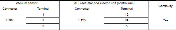
3.CHECK VACUUM SENSOR CIRCUIT
- Disconnect vacuum sensor harness connector.
- Disconnect ABS actuator and electric unit (control unit) harness connector.
- Check continuity between vacuum sensor harness connector and ABS actuator and electric unit (control unit) harness connector.
- Check continuity between vacuum sensor harness connector and ground.
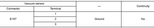
Is the inspection result normal? YES >> GO TO 4.
NO >> Repair or replace malfunctioning components.
4.CHECK TERMINAL
- Check vacuum sensor pin terminals for damage or loose connection with harness connector.
- Check ABS actuator and electric unit (control unit) pin terminals for damage or loose connection with harness connector.
Is the inspection result normal? YES >> GO TO 5.
NO >> Repair or replace malfunctioning components.
5.REPLACE VACUUM SENSOR
With CONSULT
- Connect ABS actuator and electric unit (control unit) harness connector.
- Replace vacuum sensor. Refer to BR-30, "Exploded View".
CAUTION: Always replace brake booster because vacuum sensor cannot be disassembled.
- Erase self-diagnosis result for “ABS”.
- Turn the ignition switch OFF.
- Start engine.
- Perform self-diagnosis for “ABS”.
Is DTC “C1199” detected? YES >> Replace ABS actuator and electric unit (control unit). Refer to BRC-136, "Removal and Installation".
NO >> Inspection End.
 C1198 vacuum sensor
DTC Logic
DTC DETECTION LOGIC
DTC
Display Item
Malfunction detected condition
Possible causes
C1198
VACUUM SEN CIR
When an open circuit is detected in vacuum ...
 C119A vacuum sensor
DTC Logic
DTC DETECTION LOGIC
DTC
Display Item
Malfunction detected condition
Possible causes
C119A
VACUUM SEN VOLT
When a malfunction is detected in supply power volt ...
Other materials:
Removal and installation
REAR WHEEL HUB
Exploded View
Suspension arm
Back plate
Wheel stud
Wheel hub and bearing
Disc brake rotor
Plug
Removal and Installation
REMOVAL
Wheel Hub and Bearing
Remove the wheel and tire using power tool. Refer to WT-57,
"Adjustment".
Remove t ...
Run-flat tires (if so equipped)
Run-flat tires are those tires that can be used
temporarily if they are punctured. For additional
information, refer to “Run-flat tires” in “Maintenance
and do-it-yourself.”
For additional information, refer to the tire safety
information in the Warranty Information Booklet.
WAR ...
Door sash molding
Exploded View
Front door sash molding
Rear door rear sash molding
Front door panel
Rear door panel
Roof rail side outer
Body side outer
Rear door weather strip
Rear door glass
Removal and Installation
FRONT DOOR
Removal
Remove door mirror. Refer to MIR-22, &q ...
