Nissan Rogue Service Manual: Basic inspection
DIAGNOSIS AND REPAIR WORKFLOW
Work Flow (With GR8-1200 NI)
STARTING SYSTEM DIAGNOSIS WITH GR8-1200 NI
To test the starting system, use the following special service tool:
- GR8-1200 NI Multitasking battery and electrical diagnostic station
NOTE: Refer to the diagnostic station Instruction Manual for proper starting system diagnosis procedures.
OVERALL SEQUENCE
DETAILED FLOW
NOTE: To ensure a complete and thorough diagnosis, the battery, starter motor and generator test segments must be done as a set from start to finish.
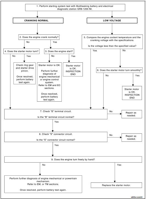
1.DIAGNOSIS WITH MULTITASKING BATTERY AND ELECTRICAL DIAGNOSTIC STATION GR8-1200 NI
Perform the starting system test with Multitasking battery and electrical diagnostic station GR8-1200 NI. For details and operating instructions, refer to diagnostic station Instruction Manual.
Test result CRANKING NORMAL>>GO TO 2.
LOW VOLTAGE>>GO TO 5.
CHARGE BATTERY>>Perform the slow battery charging procedure. (Initial rate of charge is 10A for 12 hours.) Perform battery test again. Refer to diagnostic station instruction manual.
REPLACE BATTERY>>Before replacing battery, clean the battery cable clamps and battery posts. Perform battery test again. Refer to diagnostic station instruction manual. If second test result is ŌĆ£REPLACE BATTERYŌĆØ, then do so. Perform battery test again to confirm repair.
2.CRANKING CHECK
Check that the starter motor operates properly.
Does the engine crank normally? YES >> GO TO 3.
NO >> GO TO 4.
3.ENGINE START CHECK
Check that the engine starts.
Does the engine start? YES >> Inspection End.
NO >> Perform further diagnosis of engine mechanical or engine control system. Refer to EM and EC sections. Once resolved, perform battery test again.
4.STARTER MOTOR ACTIVATION
Check that the starter motor operates.
Does the starter motor turn? YES >> Check ring gear and starter motor drive pinion. Once resolved, perform battery test again.
NO >> GO TO 7.
5.COMPARISON BETWEEN ENGINE COOLANT AND CRANKING VOLTAGE
Compare the engine coolant temperature and verify the cranking voltage is within specifications.
Minimum Specification of Cranking Voltage Referencing Coolant Temperature
| Engine coolant temperature [┬░C (┬░F)] | Voltage [V] |
| ŌłÆ30 to ŌłÆ20 (ŌłÆ22 to ŌłÆ4) | 8.6 |
| ŌłÆ19 to ŌłÆ10 (ŌłÆ2 to 14) | 9.1 |
| ŌłÆ19 to ŌłÆ10 (ŌłÆ2 to 14) | 9.5 |
| More than 1 (More than 34) | 9.9 |
Is the voltage less than the specified value? YES >> GO TO 7.
NO >> GO TO 6.
6.STARTER OPERATION
Check the starter operation.
Does the starter motor turn smoothly? YES >> Inspection End.
NO >> GO TO 7.
7.ŌĆ£BŌĆØ TERMINAL CIRCUIT INSPECTION
Check ŌĆ£BŌĆØ terminal circuit. Refer to STR-17, "Diagnosis Procedure".
Is ŌĆ£BŌĆØ terminal circuit normal? YES >> GO TO 8.
NO >> Repair as needed.
8.ŌĆ£SŌĆØ CONNECTOR CIRCUIT INSPECTION
Check ŌĆ£SŌĆØ connector circuit. Refer to STR-19, "Diagnosis Procedure"
Is ŌĆ£SŌĆØ connector circuit normal? YES >> GO TO 9.
NO >> Repair as needed.
9.ENGINE ROTATION STATUS
Check that the engine can be rotated by hand.
Does the engine turn freely by hand? YES >> Replace starter motor.
NO >> Perform further diagnosis of engine mechanical or powertrain mechanism. Once resolved, perform battery test again using Multitasking battery and electrical diagnostic station GR8-1200 NI.
Refer to the diagnostic station Instruction Manual for proper testing procedures.
Work Flow (Without GR8-1200 NI)
OVERALL SEQUENCE
DETAILED FLOW
NOTE: If any malfunction is found, immediately disconnect the battery cable from the negative terminal.
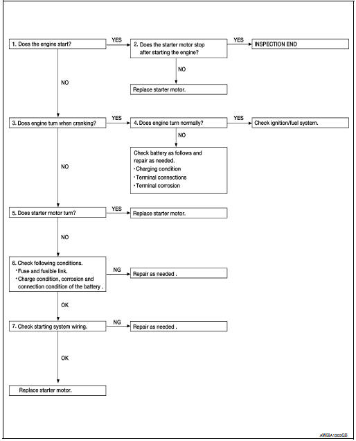
1.CHECK ENGINE START
Crank the engine and check that the engine starts.
Does the engine start? YES >> GO TO 2.
2.CHECK THAT THE STARTER MOTOR STOPS
Check that the starter motor stops after starting the engine.
Does the starter motor stop? YES >> Inspection End.
NO >> Replace starter motor. Refer to STR-21, "Removal and Installation".
3.CHECK THAT THE ENGINE TURNS WHEN CRANKING
Check that the engine turns when cranking.
Does engine turn when cranking? YES >> GO TO 4.
NO >> GO TO 5.
4.CHECK THE ENGINE SPEED WHEN CRANKING
Check that the engine speed is not low when cranking.
Does engine turn normally? YES >> Check ignition/fuel system.
NO >> Check charge condition, corrosion and connection condition of the battery.
5.CHECK STARTER MOTOR ACTIVATION
Check that the starter motor runs at cranking.
Does starter motor turn? YES >> Replace starter motor. Refer to STR-21, "Removal and Installation".
NO >> GO TO 6.
6.CHECK POWER SUPPLY CIRCUIT
Check the following conditions:
- Fuse and fusible link
- Charge condition, corrosion and connection of the battery.
Are these inspection results normal? YES >> GO TO 7.
NO >> Repair as needed.
7.CHECK STARTING SYSTEM WIRING
Check the following:
- ŌĆ£BŌĆØ terminal circuit. Refer to STR-17, "Diagnosis Procedure".
- ŌĆ£SŌĆØ terminal circuit. Refer to STR-19, "Diagnosis Procedure".
Are the inspection results normal? YES >> Replace starter motor. Refer to STR-21, "Removal and Installation".
NO >> Repair as needed.
 Wiring diagram
STARTING SYSTEM
Wiring Diagram
...

Other materials:
Voice commands
You can use voice commands to operate various
Bluetooth® Hands-Free Phone System features
using the NISSAN Voice Recognition system. For
additional information, refer to ŌĆ£NISSAN Voice
Recognition SystemŌĆØ in this section.
Voice Prompt Interrupt
While using the Voice Recognition system, the ...
Door locks/unlocks precaution
Door locks/unlocks precaution
Do not push the door handle request switch
with the Intelligent Key held in your hand as
illustrated. The close distance to the door
handle will cause the Intelligent Key system
to have difficulty recognizing that the Intelligent
Key is outside the veh ...
Wiring diagram
NAVIGATION WITH BOSE
Wiring Diagram
...
