
Nissan Rogue Service Manual: Basic inspection
DIAGNOSIS AND REPAIR WORKFLOW
Work Flow (With EXP-800 NI or GR8-1200 NI)
CHARGING SYSTEM DIAGNOSIS WITH EXP-800 NI OR GR8-1200 NI
To test the charging system, use the following special service tools:
- EXP-800 NI Battery and electrical diagnostic analyzer
- GR8-1200 NI Multitasking battery and electrical diagnostic station
NOTE: Refer to the applicable Instruction Manual for proper charging system diagnosis procedures.
OVERALL SEQUENCE
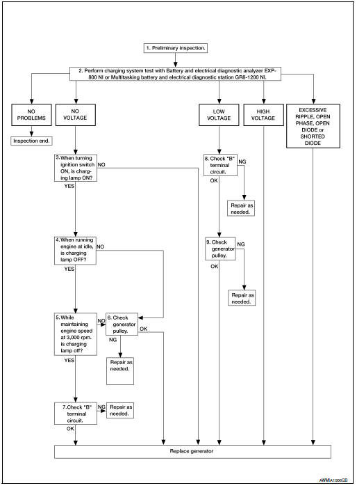
DETAILED FLOW
NOTE: To ensure a complete and thorough diagnosis, the battery, stater and generator test segments must be done as a set from start to finish.
1.PRELIMINARY INSPECTION
Perform the preliminary inspection. Refer to CHG-16, "Diagnosis Procedure".
>> GO TO 2.
2.DIAGNOSIS WITH EXP-800 NI OR GR8-1200 NI
Perform the charging system test using Multitasking battery and electrical diagnostic station GR8-1200 NI or Battery and electrical diagnostic analyzer EXP-800 NI. Refer to the applicable Instruction Manual for proper testing procedures.
Test result NO PROBLEMS>>Charging system is normal and will also show “DIODE RIPPLE� test result.
NO VOLTAGE>>GO TO 3.
LOW VOLTAGE>>GO TO 10.
HIGH VOLTAGE>>Replace generator. Refer to CHG-20, "Removal and Installation".
EXCESSIVE RIPPLE, OPEN PHASE, OPEN DIODE or SHORTED DIODE>>Replace the generator. Refer to CHG-20, "Removal and Installation". Perform “DIODE RIPPLE� test again using Multitasking battery and electrical diagnostic station GR8-1200 NI or Battery and electrical diagnostic analyzer EXP-800 NI to confirm repair.
3.INSPECTION WITH CHARGE WARNING LAMP (IGNITION SWITCH IS ON)
Turn the ignition switch ON.
Does the charge warning lamp illuminate? YES >> GO TO 4.
NO >> Replace generator. Refer to CHG-20, "Removal and Installation".
4.INSPECTION WITH CHARGE WARNING LAMP (IDLING)
Start the engine and run it at idle.
Does the charge warning lamp turn OFF? YES >> GO TO 5.
NO >> GO TO 6.
5.INSPECTION WITH CHARGE WARNING LAMP (ENGINE AT 3,000 RPM)
Increase and maintain the engine speed at 3,000 rpm.
Does the charge warning lamp remain off? YES >> GO TO 7.
NO >> GO TO 6.
6.INSPECTION OF GENERATOR PULLEY
Check generator pulley. Refer to EM-13, "Checking".
Is generator pulley normal? YES >> Replace generator. Refer to CHG-20, "Removal and Installation".
NO >> Repair as needed.
7.“B� TERMINAL CIRCUIT INSPECTION
Check “B� terminal circuit. Refer to CHG-18, "Diagnosis Procedure".
Is “B� terminal circuit normal? YES >> Replace generator. Refer to CHG-20, "Removal and Installation".
NO >> Repair as needed.
8.“B� TERMINAL CIRCUIT INSPECTION
Check “B� terminal circuit. Refer to CHG-18, "Diagnosis Procedure".
Is “B� terminal circuit normal? YES >> GO TO 9.
NO >> Repair as needed.
9.INSPECTION OF GENERATOR PULLEY
Check generator pulley. Refer to CHG-20, "Removal and Installation".
Is generator pulley normal? YES >> Replace generator. Refer to CHG-20, "Removal and Installation".
NO >> Repair as needed.
Work Flow (Without EXP-800 NI or GR8-1200 NI)
OVERALL SEQUENCE
Before performing a generator test, make sure that the battery is fully charged. A 30-volt voltmeter and suitable test probes are necessary for the test.
- Before starting, inspect the fusible link.
- Use fully charged battery.

DETAILED FLOW
1.PRELIMINARY INSPECTION
Perform the preliminary inspection. Refer to CHG-16, "Diagnosis Procedure".
>> GO TO 2.
2.INSPECTION WITH CHARGE WARNING LAMP (IGNITION SWITCH IS TURNED ON)
When ignition switch is turned ON.
Does the charge warning lamp illuminate? YES >> GO TO 3.
NO >> Replace generator. Refer to CHG-20, "Removal and Installation".
3.INSPECTION WITH CHARGE WARNING LAMP (IDLING)
Start the engine and run it at idle Does the charge warning lamp turn OFF? YES >> GO TO 4.
NO >> GO TO 5.
4.INSPECTION WITH CHARGE WARNING LAMP (ENGINE AT 2,500 RPM)
Increase and maintain the engine speed at 2,500 rpm.
Does the charge warning lamp illuminate? YES >> GO TO 5.
NO >> Inspection End.
5.MEASURE “B� TERMINAL VOLTAGE
Start engine. With engine running at 2,500 rpm, measure “B� terminal voltage.
What voltage does the measurement result show? Less than 13.0 V>>GO TO 6.
More than 16.0 V>>Replace generator. Refer to CHG-20, "Removal and Installation".
6.“B� TERMINAL CIRCUIT INSPECTION
Check “B� terminal circuit. Refer to CHG-18, "Diagnosis Procedure".
Is the inspection result normal? YES >> Replace generator. Refer to CHG-20, "Removal and Installation".
NO >> Repair as needed.
 Wiring diagram
CHARGING SYSTEM
Wiring Diagram
...

Other materials:
Basic inspection
DIAGNOSIS AND REPAIR WORKFLOW
Work Flow
DETAILED FLOW
1.COLLECT THE INFORMATION FROM THE CUSTOMER
Get the detailed information from the customer about the symptom (the
condition and the environment when
the incident/malfunction occurred) using the diagnosis worksheet.
>> GO TO 2.
2. ...
Preparation
Special Service Tool
The actual shape of the tools may differ from those illustrated here.
Tool number
(TechMate No.)
Tool name
Description
—
(J-39570)
Chassis Ear
Locating the noise
—
(J-50397)
NISSAN Squeak and Rattle
Kit
...
Fuel efficient driving tips
Follow these easy-to-use Fuel Efficient Driving
Tips to help you achieve the most fuel economy
from your vehicle.
Use Smooth Accelerator and Brake
Pedal Application
Avoid rapid starts and stops.
Use smooth, gentle accelerator and
brake application whenever possibl ...
