Nissan Rogue Service Manual: P1572 brake pedal position switch
DTC Description
DTC DETECTION LOGIC
NOTE: This self-diagnosis has the one trip detection logic. When malfunction A is detected, DTC is not stored in ECM memory. And in that case, 1st trip DTC and 1st trip freeze frame data are displayed. 1st trip DTC is erased when ignition switch OFF. And even when malfunction A is detected in two consecutive trips, DTC is not stored in ECM memory.
| DTC No. | CONSULT screen terms (Trouble diagnosis content) | DTC detecting condition | |
| P1572 | ASCD BRAKE SW (ASCD BRAKE SW) | A | When the vehicle speed is above 30 km/h (19 MPH), ON signals from the stop lamp switch and the brake pedal position switch are sent to the ECM at the same time. |
| B | Brake pedal position switch signal is not sent to ECM for extremely long time while the vehicle is driving. | ||
POSSIBLE CAUSE
- Harness or connectors
- Stop lamp switch circuit is shorted.
- Brake pedal position switch circuit is shorted.
- Stop lamp switch
- Brake pedal position switch
- Incorrect stop lamp switch installation
- Incorrect brake pedal position switch installation
- ECM
FAIL-SAFE
Not applicable
DTC CONFIRMATION PROCEDURE
1.CHECK DTC PRIORITY
If DTC P1572 is displayed with DTC P0603, P0604, P0605, P606, P0607, P060A, or P060B, first perform the trouble diagnosis for DTC P0603, P0604, P0605, P606, P0607, P060A, or P060B.
Is applicable DTC detected? YES >> Perform diagnosis of applicable. Refer to EC-93, "DTC Index".
NO >> GO TO 2.
2.PRECONDITIONING
If DTC Confirmation Procedure has been previously conducted, always perform the following procedure before conducting the next test.
- Turn ignition switch OFF and wait at least 10 seconds.
- Turn ignition switch ON.
- Turn ignition switch OFF and wait at least 10 seconds.
NOTE: Procedure for malfunction B is not described here. It takes extremely long time to complete procedure for malfunction B. By performing procedure for malfunction A, the incident that causes malfunction B can be detected. >> GO TO 3.
3.PERFORM DTC CONFIRMATION PROCEDURE FOR MALFUNCTION A
- Start engine.
- Press MAIN switch and make sure that CRUISE indicator is displayed in combination meter.
- Drive the vehicle for at least 5 consecutive seconds as per the following conditions.
CAUTION: Always drive vehicle at a safe speed.
NOTE: This procedure may be conducted with the drive wheels lifted in the shop or by driving the vehicle.
If a road test is expected to be easier, it is unnecessary to lift the vehicle.
| Vehicle speed | More than 30 km/h (19 mph) |
| Selector lev | Suitable position |
- Check DTC.
Is DTC detected? YES >> Proceed to EC-415, "Diagnosis Procedure".
NO >> GO TO 4.
4.PERFORM DTC CONFIRMATION PROCEDURE FOR MALFUNCTION B
- Drive the vehicle for at least 5 consecutive seconds as per the following conditions.
CAUTION: Always drive vehicle at a safe speed.
NOTE: This procedure may be conducted with the drive wheels lifted in the shop or by driving the vehicle.
If a road test is expected to be easier, it is unnecessary to lift the vehicle.
| Vehicle speed | More than 30 km/h (19 mph) |
| Selector lever | Suitable position |
| Driving location | Depress the brake pedal for more than five seconds so as not to come off from the above-mentioned vehicle spee |
- Check DTC.
Is DTC detected? YES >> Proceed to EC-415, "Diagnosis Procedure".
NO >> INSPECTION END
Diagnosis Procedure
1.CHECK DTC PRIORITY
If DTC P1572 is displayed with DTC P0603, P0604, P0605, P606, P0607, P060A, or P060B, first perform the trouble diagnosis for DTC P0603, P0604, P0605, P606, P0607, P060A, or P060B.
Is applicable DTC detected? YES >> Perform diagnosis of applicable. Refer to EC-93, "DTC Index".
NO >> GO TO 2.
2.CHECK OVERALL FUNCTION-1
 With CONSULT
- Turn ignition switch ON.
- Select “BRAKE SW1” in “DATA MONITOR” mode of “ENGINE” using CONSULT.
- Check “BRAKE SW1” indication as per the following conditions.
| Monitor item | Condition | Indication | |
| BRAKE SW1 | Brake pedal | Slightly depressed | OFF |
| Fully released | ON | ||
 Without CONSULT
- Turn ignition switch ON.
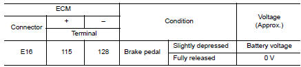
- Check the voltage between ECM harness connector terminals as per the followin
Is the inspection result normal? YES >> GO TO 3.
NO >> GO TO 4.
3.CHECK OVERALL FUNCTION-2
With CONSULT
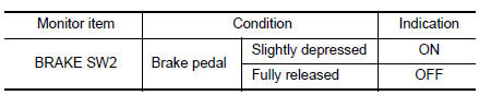
Select “BRAKE SW2” and check indication as per the following conditions.
Without CONSULT
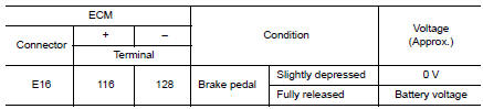
Check the voltage between ECM harness connector terminals as per the following conditions.
Is the inspection result normal? YES >> Check intermittent incident. Refer to GI-41, "Intermittent Incident".
NO >> GO TO 7.
4.CHECK BRAKE PEDAL POSITION SWITCH POWER SUPPLY
- Turn ignition switch OFF.
- Disconnect brake pedal position switch harness connector.
- Turn ignition switch ON.
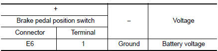
- Check the voltage between brake pedal position switch harness connector and ground.
Is the inspection result normal? YES >> GO TO 5.
NO >> Perform the trouble diagnosis for power supply circuit.
5.CHECK BRAKE PEDAL POSITION SWITCH INPUT SIGNAL CIRCUIT
- Turn ignition switch OFF.
- Disconnect ECM harness connector.
- Check the continuity between brake pedal position switch harness connector and ECM harness connector.
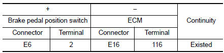
- Also check harness for short to ground and to power.
Is the inspection result normal? YES >> GO TO 6.
NO >> Repair or replace error-detected parts.
6.CHECK BRAKE PEDAL POSITION SWITCH
Check the brake pedal position switch. Refer to EC-411, "Component Inspection (Brake Pedal Position Switch)" Is the inspection result normal? YES >> Check intermittent incident. Refer to GI-41, "Intermittent Incident".
NO >> Replace brake pedal position switch. Refer to BR-20, "Exploded View".
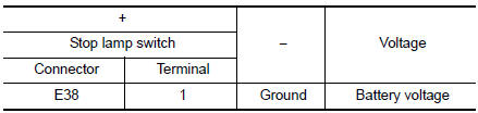
7.CHECK STOP LAMP SWITCH POWER SUPPLY CIRCUIT
- Turn ignition switch OFF.
- Disconnect stop lamp switch harness connector.
- Check the voltage between stop lamp switch harness connector and ground.
Is the inspection result normal? YES >> GO TO 8.
NO >> Perform the trouble diagnosis for power supply circuit.
8.CHECK STOP LAMP SWITCH GROUND CIRCUIT
- Check the continuity between stop lamp switch harness connector and ECM harness connector.
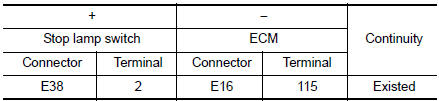
- Also check harness for short to ground and to power.
Is the inspection result normal? YES >> GO TO 9.
NO >> Repair or replace error-detected parts.
9.CHECK STOP LAMP SWITCH
Check the stop lamp switch. Refer to EC-412, "Component Inspection (Stop Lamp Switch)".
Is the inspection result normal? YES >> Check intermittent incident. Refer to GI-41, "Intermittent Incident".
NO >> Replace stop lamp switch. Refer to BR-20, "Exploded View".
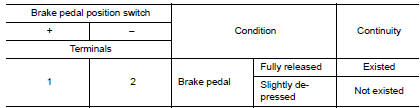
Component Inspection (Brake Pedal Position Switch)
1.CHECK BRAKE PEDAL POSITION SWITCH-1
- Turn ignition switch OFF.
- Disconnect brake pedal position harness connector.
- Check the continuity between brake pedal position switch terminals as per the following conditions.
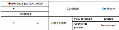
Is the inspection result normal? YES >> INSPECTION END
NO >> GO TO 2.
2.CHECK BRAKE PEDAL POSITION SWITCH-2
- Adjust brake pedal position switch installation. Refer to BR-15, "Adjustment".
- Check the continuity between brake pedal position switch terminals as per the following conditions.
Is the inspection result normal? YES >> INSPECTION END NO >> Replace brake pedal position switch. Refer to BR-20, "Exploded View".
Component Inspection (Stop Lamp Switch)
1.CHECK STOP LAMP SWITCH-1
- Turn ignition switch OFF.
- Disconnect stop lamp switch harness connector.
- Check the continuity between stop lamp switch terminals as per the following conditions.
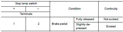
Is the inspection result normal? YES >> INSPECTION END
NO >> GO TO 2.
2.CHECK STOP LAMP SWITCH-2
- Adjust stop lamp switch installation. Refer to BR-7, "Inspection".
- Check the continuity between stop lamp switch terminals as per the following conditions.
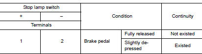
Is the inspection result normal? YES >> INSPECTION END
NO >> Replace stop lamp switch. Refer to BR-20, "Exploded View".
 P1568 signal invalid
DTC Description
DTC DETECTION LOGIC
DTC No.
CONSULT screen terms
(Trouble diagnosis content)
DTC detecting condition
P1568
ICC COMMAND VALUE
(Intelligent cruise contro ...
 P1574 ASCD vehicle speed sensor
Description
The ECM receives two vehicle speed sensor signals via CAN communication line.
One is sent from combination
meter, and the other is from TCM (Transmission control module). The ECM uses ...
Other materials:
Tire Pressure Monitoring System (TPMS)
Each tire, including the spare (if provided),
should be checked monthly when cold and inflated
to the inflation pressure recommended by
the vehicle manufacturer on the vehicle placard
or tire inflation pressure label. (If your vehicle has
tires of a different size than the size indicated on
th ...
Air breather
Exploded View
Air breather
Air breather hose
Air breather tube
Transaxle assembly
: Vehicle front
Removal and Installation
REMOVAL
Remove air cleaner and air duct. Refer to EM-24, "Removal and
Installation".
Remove air breather hose from transaxle a ...
P0850 PNP switch
Description
Transmission range switch is turn ON when the selector lever is P or N.
ECM detects the position because the continuity of the line (the ON) exists.
DTC Description
DTC DETECTION LOGIC
DTC No.
CONSULT screen terms
(Trouble diagnosis content)
DTC detecting condition ...
