Nissan Rogue Owners Manual: Instrument panel
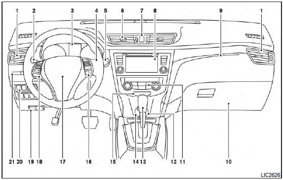
- Vent
- Headlight/fog light (if so equipped)/turn signal switch
- Meters, gauges, warning/indicator lights and Vehicle Information Display
- Windshield wiper/washer switch and rear window wiper/washer switch /Ignition switch (if so equipped)
- Push-button ignition switch (if so equipped)
- Vent
- Hazard warning flasher switch
- Radio /Navigation system* (if so equipped)
- Front passenger supplemental air bag
- Glove box
- Heater and air conditioning controls
- Power outlet
- Shift lever
- Auxiliary jack /USB port
- Front passenger air bag status light
- Cruise control main/set switches (/Bluetooth Hands-Free Phone System (if so equipped)
- Driver supplemental air bag/Horn (, )
- Control panel and Vehicle Information Display switches
- Hood release /Fuel door release
- Vehicle Dynamic Control (VDC) OFF switch Sport mode switch ECO mode switch (if so equipped) Power liftgate switch (if so equipped) (P.3-28) Power liftgate main switch (if so equipped) Warning systems switch (if so equipped) All-Wheel Drive (AWD) lock switch (if so equipped) Hill descent control switch (if so equipped)
- Instrument brightness control /Twin trip odometer reset switch
*: Refer to the separate Navigation System Owner’s Manual (if so equipped).
Refer to the page number indicated in parentheses for operating details.
 Passenger compartment
Glove box
Map lights
Console box
Power panoramic moonroof (if so equipped)
Luggage hooks
Center armrest (2nd row)
Seats
Cup holders ...
 Engine compartment check locations
QR25DE engine
Engine coolant reservoir
Engine oil filler cap
Brake fluid reservoir
Battery
Air cleaner
Fuse/Fusible link box
Radiator cap ...
Other materials:
C1604 torque sensor
DTC Logic
DTC DETECTION LOGIC
DTC
Display item
Malfunction detected condition
Possible cause
C1604
TORQUE SENSOR
When torque sensor output signal is malfunctioning.
Harness or connector
Torque sensor
EPS control unit
...
NISSAN Vehicle Immobilizer System keys
You can only drive your vehicle using the master
keys which are registered to the NISSAN Vehicle
Immobilizer System components in your vehicle.
These keys have a transponder chip in the key
head.
The master key can be used for all the locks.
Never leave these keys in the vehicle.
Additi ...
Troubleshooting guide
Verify the location of all Intelligent Keys that are
programmed for the vehicle. If another Intelligent
Key is in range or inside the vehicle, the vehicle
system may respond differently than expected.
Symptom
Possible Cause
Remedy
When stopping the engine
The Shift to Pa ...
