Nissan Rogue Service Manual: U1040 ENG comm circuit
DTC Description
DTC DETECTION LOGIC
| DTC No. | CONSULT screen terms (Trouble diagnosis content) | DTC detecting condition |
| U1040 | ENG COMM CIRCUIT (Engine communication circuit) | ECM cannot transmit a communication signal to generator. |
POSSIBLE CAUSE
- Harness or connectors (LIN communication circuit is open or shorted.)
- ECM
FAIL-SAFE
Not applicable
DTC CONFIRMATION PROCEDURE
1.PRECONDITIONING
If DTC Confirmation Procedure has been previously conducted. always perform the following procedure before conducting the next test.
- Turn ignition switch OFF and wait at least 10 seconds.
- Turn ignition switch ON.
- Turn ignition switch OFF and wait at least 10 seconds.
>> GO TO 2.
2.PERFORM DTC CONFIRMATION PROCEDURE
- Turn ignition ON and wait at least 10 seconds.
- Check DTC.
Is DTC detected? YES >> Proceed to EC-171, "Diagnosis Procedure".
NO >> INSPECTION END
Diagnosis Procedure
1.CHECK LIN COMMUNICATION CIRCUIT
- Turn ignition switch OFF.
- Disconnect ECM harness connector and generator harness connector.
- Check the continuity between ECM harness connector and generator harness connector.
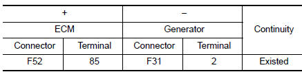
- Also check harness for short to power and short to ground.
Is the inspection result normal? YES >> GO TO 2.
NO >> Repair or replace error-detected parts.
2.REPLACE GENERATOR
- Replace generator. Refer to CHG-20, "Removal and Installation".
- Erase DTC.
- Perform DTC confirmation procedure again. Refer to EC-171, "DTC Description".
Is DTC detected again? YES >> Replace ECM. Refer to EC-499, "Removal and Installation".
NO >> INSPECTION END
 U1001 CAN comm circuit
Description
CAN (Controller Area Network) is a serial communication line for real time
application. It is an on-vehicle multiplex
communication line with high data communication speed and excellen ...
 U1044 ENG comm circuit
DTC Description
DTC DETECTION LOGIC
DTC No.
CONSULT screen terms
(Trouble diagnosis content)
DTC detecting condition
U1044
ENG COMM CIRCUIT
(Engine communication circu ...
Other materials:
Driving safety precautions
Your NISSAN is designed for both normal and
off-road use. However, avoid driving in deep water
or mud as your NISSAN is mainly designed for
leisure use, unlike a conventional off-road vehicle.
Remember that two-wheel drive models are less
capable than all-wheel drive models for rough
road dr ...
TPMS
Symptom Table
LOW TIRE PRESSURE WARNING LAMP SYMPTOM CHART
Diagnosis
items
Symptom
(Power switch ON)
Low tire pressure warning lamp
Cause
Action
Low tire pressure
warning
lamp
The low tire pressure
warning lamp
illuminates for 1
second, then turn ...
LATCH (Lower Anchors and Tethers for CHildren) System
LATCH system lower anchor locations - bench seat
Your vehicle is equipped with special anchor
points that are used with LATCH system compatible
child restraints. This system may also be
referred to as the ISOFIX or ISOFIX compatible
system. With this system, you do not have to use
a vehicl ...
