Nissan Rogue Service Manual: System description
SYSTEM
System Description
SYSTEM DIAGRAM
SYSTEM DESCRIPTION
- The BCM has a CAN gateway function.
- The BCM communicates between two CAN communication circuits.
- The BCM selects and transmits only necessary information.
DIAGNOSIS SYSTEM (CAN GATEWAY)
CONSULT Function
APPLICATION ITEM
CONSULT performs the following functions via CAN communication with CAN gateway.
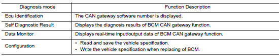
ECU IDENTIFICATION
The CAN gateway part number is displayed.
SELF DIAGNOSTIC RESULT
Refer to LAN-76, "DTC Index".
- When ŌĆ£CRNTŌĆØ is displayed on self-diagnosis result
- The system is presently malfunctioning.
- When ŌĆ£PASTŌĆØ is displayed on self-diagnosis result
- System malfunction in the past is detected, but the system is presently normal.
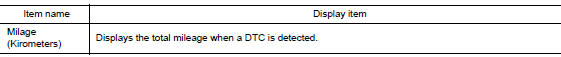
Freeze Frame Data (FFD)
When DTC is detected, a vehicle state shown below is recorded and displayed on CONSULT.
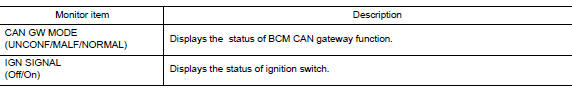
DATA MONITOR
CONFIGURATION
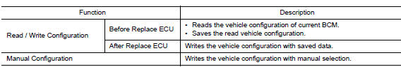
CAUTION: Follow the instructions listed below. Failure to do this may cause malfunctions to the BCM.:
- When replacing BCM you must perform ŌĆ£Read / Write ConfigurationŌĆØ or ŌĆ£Manual ConfigurationŌĆØ with CONSULT.
- Complete the procedure of ŌĆ£Read / Write ConfigurationŌĆØ or ŌĆ£Manual ConfigurationŌĆØ in order.
- If you set incorrect ŌĆ£Read / Write ConfigurationŌĆØ or ŌĆ£Manual ConfigurationŌĆØ, incidents might occur.
- Configuration is different for each vehicle model. Confirm configuration of each vehicle model.
- Never perform ŌĆ£Read / Write ConfigurationŌĆØ or ŌĆ£Manual ConfigurationŌĆØ except for new BCM.
 Precaution
Precaution for Supplemental Restraint System (SRS) "AIR BAG" and "SEAT
BELT
PRE-TENSIONER"
The Supplemental Restraint System such as ŌĆ£AIR BAGŌĆØ and ŌĆ£SEAT BELT PRE-TENSIONE ...
 ECU diagnosis information
CAN GATEWAY
Reference Value
VALUES ON THE DIAGNOSIS TOOL
NOTE:
The following table includes information (items) inapplicable to this vehicle.
For information (items) applicable
to this vehicle, ...
Other materials:
Symptom diagnosis
INTERIOR LIGHTING SYSTEM SYMPTOMS
Symptom Table
CAUTION:
Perform the self-diagnosis with CONSULT before the symptom diagnosis. Perform
the trouble diagnosis
if any DTC is detected.
Symptom
Possible cause
Inspection item
All the following lamps do not turn ON. ...
Precaution
Precaution for Supplemental Restraint System (SRS) "AIR BAG" and "SEAT
BELT
PRE-TENSIONER"
The Supplemental Restraint System such as ŌĆ£AIR BAGŌĆØ and ŌĆ£SEAT BELT PRE-TENSIONERŌĆØ,
used along
with a front seat belt, helps to reduce the risk or severity of injury to the
...
ECU diagnosis information
CAN GATEWAY
Reference Value
VALUES ON THE DIAGNOSIS TOOL
NOTE:
The following table includes information (items) inapplicable to this vehicle.
For information (items) applicable
to this vehicle, refer to CONSULT display items.
DTC Index
...
