Nissan Rogue Service Manual: Steering column
Exploded View

- Steering column
- Floor cover
- Floor seal
Removal and Installation
CAUTION:
- Any time the ignition switch has been disconnected, removed or installed, the keys must be re-registered in the BCM. Refer to CONSULT operations manual.
- Do not cause impact to the steering column during removal and installation.
REMOVAL
- Set front wheels and tires in the straight-ahead position.
- Place the tilt to the highest level.
- Remove combination switch. Refer to BCS-76, "Removal and Installation" (WITH INTELLIGENT KEY SYSTEM), BCS-136, "Removal and Installation" (WITHOUT INTELLIGENT KEY SYSTEM).
- Remove instrument lower panel LH. Refer to IP-22, "Removal and Installation".
- Disconnect the harness connectors from the steering column.
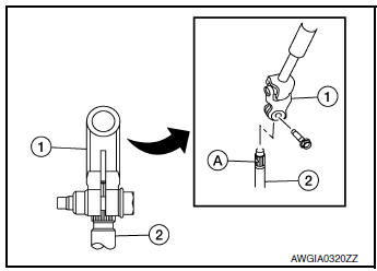
- Remove bolt and separate steering column from steering gear pinion
shaft.
CAUTION: Do not move the steering gear during removal and installation of the steering column.
- Remove nuts and remove steering column.
INSTALLATION
Installation is in the reverse order of removal.
CAUTION:
- When connecting the steering column yoke (1) to the steering gear pinion shaft (2), make sure that the groove (A) lines up with the steering column yoke hole.
- Make sure the bolt is in the correct direction, as shown, and engages the steering gear pinion shaft groove (A).
- When installing the steering column, finger-tighten all of the lower bracket and joint retaining bolts; then tighten them to specification. Do not apply undue stress to the steering column.
- Replace the steering column if it has been droped or sustained an impact.
- After installation, turn steering wheel to make sure it moves
smoothly while turning to the left and right stops.
Make sure the number of turns are the same from the straight-forward position to left and right stops. Make sure that the steering wheel is in a neutral position when driving straight ahead.
- When installing steering column to steering member, install nut from front of vehicle.
- After installing the steering column, check the tilt mechanism for proper operation.
- Adjust the neutral position of the steering angle sensor. Refer to BRC-70, "Work Procedure".
Inspection
INSPECTION AFTER REMOVAL
- Check each part of steering column for damage or other malfunctions. Replace if there are any abnormal conditions. Refer to ST-9, "Inspection".
INSPECTION AFTER INSTALLATION
- Check each part of steering column for damage or other malfunctions. Replace if there are any abnormal conditions. Refer to ST-9, "Inspection".
- Check the steering wheel play, neutral position steering wheel, steering wheel turning force, and front wheel turning angle. Refer to ST-7, "Inspection".
 Steering wheel
Exploded View
Steering wheel
Removal and Installation
REMOVAL
Set the front wheels and tires in the straight-ahead position.
Remove driver air bag module. Refer to SR-12, ...
 Steering gear and linkage
Exploded View
REMOVAL AND INSTALLATION
Cotter pin
Steering gear
Heat shiel
Removal and Installation
REMOVAL
Set the front wheels and tires to the straight-ahea ...
Other materials:
Unit disassembly and assembly
TRANSFER COVER
Exploded View
Filler plug
Gasket
Drain plug
Oil seal
Transfer cover
Oil seal
O-ring
Ring gear bearing adjusting shim
(transfer cover side)
Ring gear bearing (transfer cover
side)
Ring gear shaft oil seal
...
C1109 power and ground system
DTC Logic
DTC DETECTION LOGIC
DTC
Display Item
Malfunction detected condition
Possible causes
C1109
BATTERY VOLTAGE
[ABNORMAL]
When ignition voltage is 10 V or less.
When ignition voltage is 16 V or more.
Harness or connector ...
AM radio reception
AM signals, because of their low frequency, can
bend around objects and skip along the ground.
In addition, the signals can be bounced off the
ionosphere and bent back to earth. Because of
these characteristics, AM signals are also subject
to interference as they travel from transmitter
to r ...
