Nissan Rogue Service Manual: Steering gear and linkage
Exploded View
REMOVAL AND INSTALLATION

- Cotter pin
- Steering gear
- Heat shiel
Removal and Installation
REMOVAL
- Set the front wheels and tires to the straight-ahead position.
- Remove the floor cover. Refer to ST-12, "Exploded View".
- Remove the floor seal. Refer to ST-12, "Exploded View".
- Remove the joint retaining bolt and separate the steering column
yoke from the steering gear pinion shaft.
Refer to ST-12, "Exploded View".
- Remove the cotter pins (LH/RH), nuts (LH/RH) and disconnect the outer sockets (LH/RH).
- Separate the stabilizer connecting rods (LH/RH) from the stabilizer bar. Refer to FSU-20, "Exploded View".
- Disconnect the harness connector for oxygen sensor 2. Refer to EX-5, "Exploded View"
- Remove the front exhaust tube. Refer to EX-5, "Exploded View".
- Remove the center exhaust tube. Refer to EX-5, "Exploded View".
- . Remove the lower torque rod. Refer to EM-81, "Exploded View".
- . Remove front suspension member stay and support the front suspension using a suitable jack. Refer to FSU-20, "Exploded View".
- Remove bolts and remove the steering gear.
INSTALLATION
Installation is in the reverse order of removal.
CAUTION:
- With the steering linkage disconnected, the spiral cable may snap by turning the steering wheel beyond the limited number of turns.
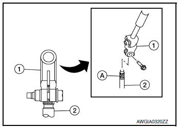
- When connecting the steering column yoke (1) to the steering gear pinion shaft (2), be sure that gap (A) lines up with the joint retaining bolt hole.
- When installing the steering column, finger-tighten all of the lower bracket and joint retaining bolts; then tighten them to specification. Do not apply undue stress to the steering column.
- Do not reuse steering gear nuts.
- Check wheel alignment. Refer to FSU-7, "Inspection".
- Adjust the neutral position of the steering angle sensor. Refer to BRC-70, "Work Procedure".
Inspection
INSPECTION AFTER INSTALLATION
- Check if steering wheel turns smoothly when it is turned several times fully to the end of the left and right.
- Check the steering wheel play, neutral position steering wheel, steering wheel turning force, and front wheel turning angle. Refer to ST-7, "Inspection".
 Steering column
Exploded View
Steering column
Floor cover
Floor seal
Removal and Installation
CAUTION:
Any time the ignition switch has been disconnected, removed or
install ...
 Unit disassembly and assembly
STEERING GEAR AND LINKAGE
Exploded View
DISASSEMBLY AND ASSEMBLY
Steering gear
Inner boot clamp
Boot
Outer boot clamp
Outer socket
Disassembly and Assem ...
Other materials:
Precaution
Precaution for Supplemental Restraint System (SRS) "AIR BAG" and "SEAT
BELT
PRE-TENSIONER"
The Supplemental Restraint System such as “AIR BAG” and “SEAT BELT PRE-TENSIONER”,
used along
with a front seat belt, helps to reduce the risk or severity of injury to the
...
Disassembly and assembly
FUEL LEVEL SENSOR UNIT
Exploded View
Fuel Level Sensor Unit
Fuel filter and pump assembly
Fuel level sensor unit
Float arm assembly
Fuel tank temperature sensor
Disassembly and Assembly
NOTE:
Fuel level sensor unit and fuel tank temperature sensor are replaced as and
assembl ...
Idle air volume learning
Description
Idle Air Volume Learning is a function of ECM to learn the idle air volume
that keeps each engine idle speed
within the specific range. It must be performed under any of the following
conditions:
Each time electric throttle control actuator or ECM is replaced.
Idle spee ...
