Nissan Rogue Service Manual: Side air bag (satellite) sensor
Exploded View
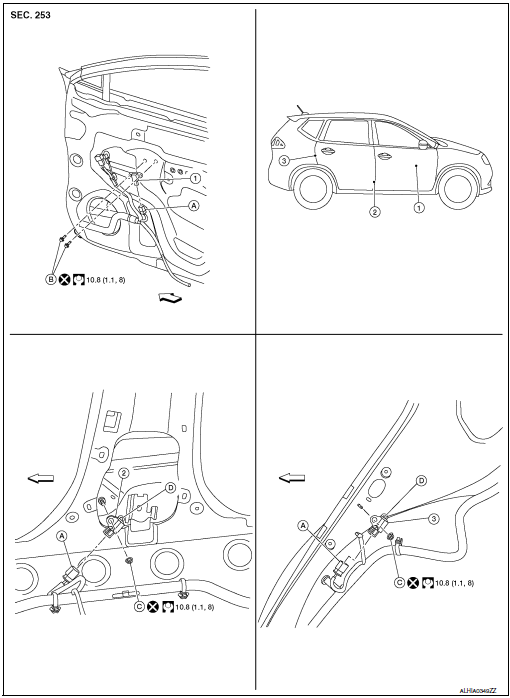
- Front door satellite sensor
- Front side air bag satellite sensor
- Rear side satellite sensor
- Satellite sensor harness connector
- Bolt
- Nut
- Pawl
 Front
Front
NOTE: RH side shown, LH side similar.
Removal and Installation
WARNING:
- Before servicing the SRS, turn ignition switch OFF, disconnect both battery terminals then wait at least three minutes.
- Do not use air tools or electric tools for servicing.
FRONT SIDE AIR BAG SATELLITE SENSOR
Removal
- Disconnect negative and positive battery terminals, then wait at least three minutes. Refer to PG-77, "Removal and Installation".
- Place aside the front seat belt retractor.
- Remove the front side air bag satellite sensor nut.
CAUTION: Do not reuse the front side air bag satellite sensor nut.
- Disconnect the harness connector from the front side air bag satellite sensor and remove.
CAUTION:
- Replace the front side air bag satellite sensor if it has been dropped or sustained an impact.
- Do not strike the front side air bag satellite sensor.
Installation
Installation is in the reverse order of removal.
- Position the front side air bag satellite sensor using the pawl before tightening the nut to specification.
CAUTION:
- Do not reuse the front side air bag satellite sensor nut.
- Do not damage the harness connector during installation.
- After installation is complete, check that no system malfunction is detected causing the air bag warning lamp to illuminate.
- If a malfunction is indicated by the air bag warning lamp after repair or replacement of the malfunctioning parts, perform the SRS final check. Refer to SRC-18, "Trouble Diagnosis with CONSULT".
REAR SIDE AIR BAG SATELLITE SENSOR
Removal
- Disconnect negative and positive battery terminals, then wait at least three minutes. Refer to PG-77, "Removal and Installation".
- Remove the luggage side lower finisher. Refer to INT-34, "LUGGAGE SIDE LOWER FINISHER : Removal and Installation - With Third Row Seat" (WITH THIRD ROW SEAT), INT-34, "LUGGAGE SIDE LOWER FINISHER : Removal and Installation - With Third Row Seat" (WITHOUT THIRD ROW SEAT).
- Remove the rear side air bag satellite sensor bolt.
CAUTION: Do not reuse the rear side air bag satellite sensor bolt.
- Disconnect the harness connector from the rear side air bag satellite sensor and remove.
CAUTION:
- Replace the rear side air bag satellite sensor if it has been dropped or sustained an impact.
- Do not strike the rear side air bag satellite sensor.
Installation Installation is in the reverse order of removal.
- Position the rear side air bag satellite sensor using the pawl before tightening the bolt to specification.
CAUTION:
- Do not reuse the rear side air bag satellite sensor bolt.
- Do not damage the harness connector during installation.
- After installation is complete, check that no system malfunction is detected causing the air bag warning lamp to illuminate.
- If a malfunction is indicated by the air bag warning lamp after repair or replacement of the malfunctioning parts, perform the SRS final check. Refer to SRC-18, "Trouble Diagnosis with CONSULT".
FRONT DOOR SATELLITE SENSOR
Removal
- Disconnect negative and positive battery terminals, then wait at least three minutes. Refer to PG-77, "Removal and Installation".
- Remove the front door finisher. Refer to INT-15, "Removal and Installation".
- Partially remove front door vapor barrier.
- Remove the front door satellite sensor bolts.
CAUTION: Do not reuse the front door satellite sensor bolts.
- Disconnect the harness connector from the front door satellite sensor and remove.
CAUTION:
- Replace the front door satellite sensor if it has been dropped or sustained an impact.
- Do not strike the front door satellite sensor.
Installation
Installation is in the reverse order of removal.
CAUTION:
- Do not reuse the front door satellite sensor bolts.
- Do not damage the harness connector during installation.
- After installation is complete, check that no system malfunction is detected causing the air bag warning lamp to illuminate.
- If a malfunction is indicated by the air bag warning lamp after repair or replacement of the malfunctioning parts, perform the SRS final check. Refer to SRC-18, "Trouble Diagnosis with CONSULT".
 Crash zone sensor
Exploded View
Crash zone sensor
Crash zone sensor harness
connector
Bracket
Removal and Installation
WARNING:
Before servicing the SRS, turn ignition switc ...
 Air bag diagnosis sensor unit
Exploded View
Diagnosis sensor unit
Front
Removal and Installation
WARNING:
Before servicing the SRS, turn ignition switch OFF, disconnect
both battery terminals then wait ...
Other materials:
Power window control system symptoms
Symptom Table
Symptom
Reference page
None of the power windows can be operated using any switch.
Refer to PWC-55, "Diagnosis Procedure".
Driver side power window alone does not operate.
Refer to PWC-56, "Diagnosis Procedure".
Fr ...
Does not operate
Description
VDC function, TCS function, ABS function, EBD function, Brake limited slip
differential (BLSD) function, Brake
assist function, hill start assist function or Brake force distribution function
does not operate.
Diagnosis Procedure
CAUTION:
VDC function, TCS function, ABS ...
Preparation
Special Service Tool
The actual shape of the tools may differ from those tools illustrated here.
Tool number
(TechMate No.)
Tool name
Description
—
(J-50190)
Signal Tech II
Activate and display TPMS transmitter IDs
Display tire ...
