Nissan Rogue Service Manual: Removal and installation
AWD CONTROL UNIT
Exploded View
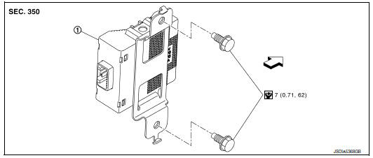
1 AWD control unit
 : Vehicle front
 : N·m (kg-m, in-lb)
Removal and Installation
REMOVAL
- Remove luggage side lower finisher (LH). Refer to INT-33, "Exploded View".
- Disconnect AWD control unit harness connector.
- Remove AWD control unit bolts (
 ).
).
NOTE: AWD control unit is located on the back side of body panel.
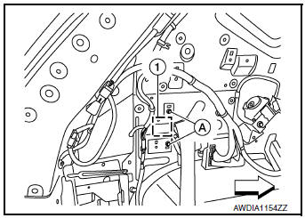
: Front
- Remove AWD control unit.
INSTALLATION
Installation is in the reverse order of removal.
CAUTION:
- Do not drop or shock AWD control unit.
- When replacing AWD control unit, perform writing unit characteristic. Refer to DLN-35, "Work Procedure".
AWD LOCK SWITCH
Exploded View
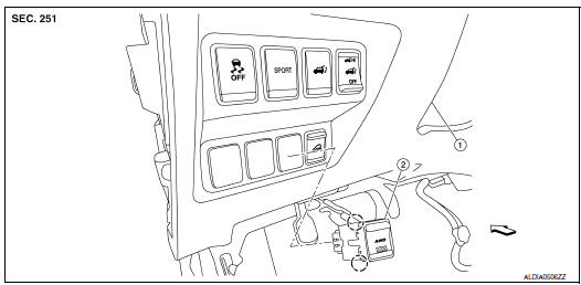
- Instrument lower panel LH
- AWD lock switch
Front
 Pawl
Pawl
Removal and Installation
REMOVAL
- Remove instrument lower panel LH. Refer to IP-22, "Removal and Installation".
- Disconnect AWD lock switch harness connector (A).
- Remove AWD lock switch from lower switch bracket (2).

: Pawls
INSTALLATION
Install in the reverse order of removal.
TRANSFER COVER OIL SEAL
Removal and Installation
NOTE:
- Replacement on vehicle may cause damage to transfer cover, and may cause a transfer oil leak.
- If transfer cover oil seal requires replacement, remove the transfer assembly from the vehicle before replacing transfer cover oil seal. Refer to DLN-73, "Disassembly".
 Periodic maintenance
TRANSFER OIL
Inspection
TRANSFER OIL LEAKS
Check that transfer oil is not leaking from transfer assembly or around it.
TRANSFER OIL LEVEL
CAUTION:
Do not start engine while checking transfer oil ...
 Unit removal and installation
TRANSFER ASSEMBLY
Exploded View
1 Transfer assembly
: N·m (kg-m, ft-lb)
*: Apply anti-corrosion oil.
Removal and Installation
NOTE:
When removing components such as hoses, tubes/lines, etc ...
Other materials:
Precaution]
Precaution for Supplemental Restraint System (SRS) "AIR BAG" and "SEAT
BELT
PRE-TENSIONER"
The Supplemental Restraint System such as “AIR BAG” and “SEAT BELT PRE-TENSIONER”,
used along
with a front seat belt, helps to reduce the risk or severity of injury to the
...
P0453 EVAP control system pressure sensor
DTC Description
DTC DETECTION LOGIC
DTC No.
CONSULT screen terms
(Trouble diagnosis content)
DTC detecting condition
P0453
EVAP SYS PRES SEN
(Evaporative emission system pressure
sensor/switch high)
An excessively high voltage from the sensor is sent to ECM.
...
USB (Universal Serial Bus) Connection Port (models with Navigation System)
(if so equipped)
USB (Universal Serial Bus) Connection Port (models with Navigation System)
Connecting a device to the USB
Connection Port
WARNINGDo not connect, disconnect, or operate the
USB device while driving. Doing so can be
a distraction. If distracted you could lose
control of your ...
