Nissan Rogue Service Manual: Removal and installation
BCM (BODY CONTROL MODULE)
Removal and Installation
CAUTION: Before replacing the BCM, perform ŌĆ£READ CONFIGURATIONŌĆØ to save or print current vehicle specification.
Refer to BCS-120, "ADDITIONAL SERVICE WHEN REPLACING CONTROL UNIT (BCM) : Work Procedure".
REMOVAL
- Disconnect the negative battery terminal. Refer to PG-77, "Removal and Installation".
- Remove the instrument lower panel LH. Refer to IP-22, "Removal and Installation".
- Remove the bolt (A), then pull out the BCM (1).
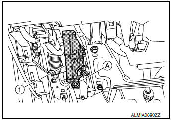
- Disconnect the harness connectors from the BCM and remove.
INSTALLATION
Installation is in the reverse order of removal.
CAUTION:
- When replacing BCM, perform ŌĆ£WRITE CONFIGURATIONŌĆØ Refer to BCS-121, "CONFIGURATION (BCM) : Work Procedure".
- When replacing BCM, perform the system initialization (NATS). Refer to the CONSULT immobilizer mode and follow the on-screen instructions.
- When replacing BCM, if new BCM does not come with keyfobs attached, all existing keyfobs must be re-registered. Refer to the CONSULT immobilizer mode and follow the on screen instructions.
COMBINATION SWITCH
Exploded View
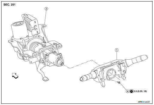
- Combination switch
- Steering column
- Screw
 Front
Front
Removal and Installation
REMOVAL
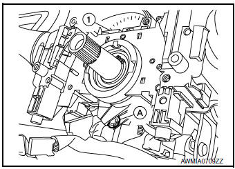
- Remove the steering angle sensor. Refer to BRC-139, "Removal and Installation".
- Disconnect harness connector from combination switch.
- Remove screw (A) and combination switch (1).
INSTALLATION
Installation is in the reverse order of removal
 Symptom diagnosis
COMBINATION SWITCH SYSTEM SYMPTOMS
Symptom Table
Perform the data monitor of CONSULT to check for any malfunctioning
item.
Check the malfunction combinations.
Identify the ma ...
 LAN System
...
Other materials:
Engine coolant
Inspection
LEVEL
Check that the reservoir tank engine coolant level is within the
ŌĆ£MINŌĆØ to ŌĆ£MAXŌĆØ when the engine is cool.
(A) : MAX
(B) : MIN
Adjust the engine coolant level if necessary.
CAUTION:
Refill Genuine NISSAN Long Life Antifreeze/Coolant (blue) or
equiva ...
C1121, C1123, C1125, C1127 ABS out valve system
DTC Logic
DTC DETECTION LOGIC
DTC
Display Item
Malfunction detected condition
Possible causes
C1121
FR LH OUT ABS SOL
When a malfunction is detected in front LH ABS OUT
valve.
Harness or connector
ABS actuator and electric unit
(control u ...
P0420 three way catalyst function
DTC Description
DTC DETECTION LOGIC
The ECM monitors the switching frequency ratio of air fuel ratio (A/F)
sensor 1 and heated oxygen sensor 2.
A three way catalyst (manifold) with high oxygen storage capacity
will indicate a low switching frequency of heated oxygen sensor 2.
As oxygen sto ...
