
Nissan Rogue Service Manual: How to follow trouble diagnoses
Description
NOTICE: Trouble diagnoses indicate work procedures required to diagnose problems effectively. Observe the following instructions before diagnosing.
- Before performing trouble diagnoses, read the “Work Flow� in each section.
- After repairs, re-check that the problem has been completely eliminated.
- Refer to Component Parts and Harness Connector Location for the Systems described in each section for identification/location of components and harness connectors.
- When checking circuit continuity, ignition switch should be OFF.
- Refer to the Circuit Diagram for quick pinpoint check.
If you need to check circuit continuity between harness connectors in more detail, such as when a sub-harness is used, refer to Wiring Diagram in each individual section and Harness Layout in PG section for identification of harness connectors.
- Before checking voltage at connectors, check battery voltage.
- After accomplishing the Diagnosis Procedures and Electrical Components Inspection, make sure that all harness connectors are reconnected as they were.
How to follow test groups in trouble diagnosis
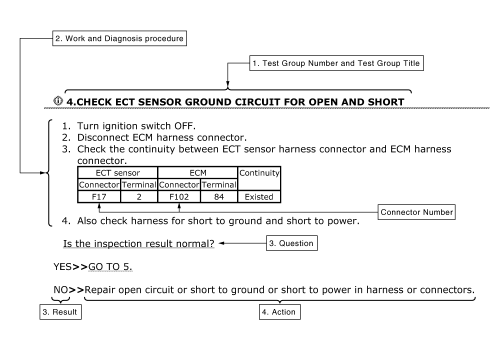
- Test group number and test group title
- Test group number and test group title are shown in the upper portion of each test group.
- Work and diagnosis procedure
- Start to diagnose a problem using procedures indicated in enclosed test groups.
- Questions and results
- Questions and required results are indicated in test group.
- Action
- Next action for each test group is indicated based on result of each question.
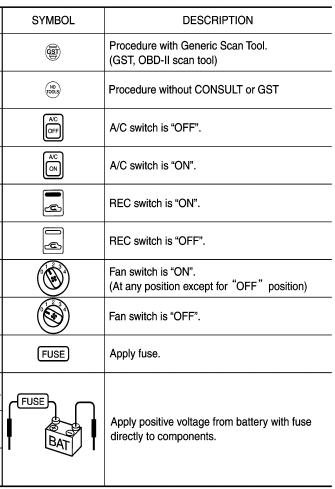
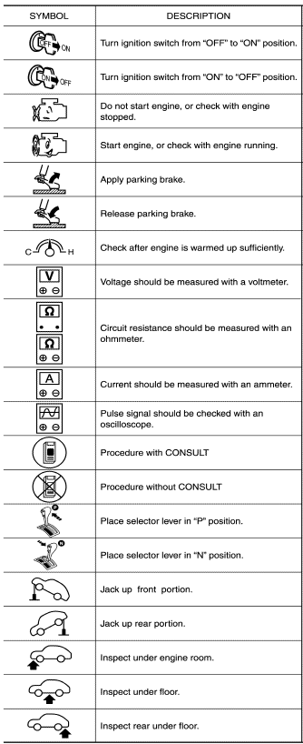
Key to symbols signifying measurements or procedures


 How to use this manual
How to use this manual
Description
This volume explains “Removal, Disassembly, Installation, Inspection and
Adjustment� and “Trouble Diagnoses�.
Terms
The captions WARNING and CAUTI ...

Other materials:
B0096 front side air bag satellite sensor RH
Description
DTC B0096 FRONT SATELLITE SENSOR RH
The front side air bag satellite sensor RH is wired to the air bag diagnosis
sensor unit. The air bag diagnosis
sensor unit will monitor the front side air bag satellite sensor RH for internal
failures and its circuits for communication
errors. ...
Remote keyless entry system (if so equipped)
WARNING
Radio waves could adversely affect
electric medical equipment. Those who
use a pacemaker should contact the
electric medical equipment manufacturer
for the possible influences before
use.
The remote keyless entry keyfob transmits
radio waves ...
iPod®* player operation with Navigation System (if so equipped)
iPod®* player operation with Navigation System
Connecting iPod®
WARNINGDo not connect, disconnect, or operate the
USB device while driving. Doing so can be
a distraction. If distracted you could lose
control of your vehicle and cause an accident
or serious injury.
& ...
