Nissan Rogue Service Manual: Parking brake shoe
Exploded View
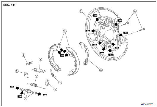
- Back plate
- Parking brake shoe
- Brake strut
- Return spring
- Spring
- Return spring to brake strut
- Adjuster
- Toggle lever
- Anti-rattle pin
 : Apply PBC (Poly Butyl
Cuprysil) grease or silicone-based grease
: Apply PBC (Poly Butyl
Cuprysil) grease or silicone-based grease
Removal and Installation
REMOVAL
WARNING: Clean dust on the parking brake shoes with a vacuum dust collector to minimize the hazard of airborne particles or other materials.
- Remove the rear wheel and tire using power tool. Refer to WT-60, "Removal and Installation".
- Remove the brake caliper torque member bolts, leaving the brake
hose attached. Position the caliper
aside with wire. Refer to BR-43, "BRAKE CALIPER ASSEMBLY : Removal and
Installation".
CAUTION: Do not depress the brake pedal while the caliper assembly is removed.
- Put alignment marks on the disc brake rotor and on the wheel hub
and bearing and remove the disc brake
rotor.
CAUTION: Do not drop the disc brake rotor.
- If disc brake rotor cannot be removed, remove as follows:
- Secure the disc brake rotor with wheel nuts and remove the adjusting hole plug.
- Using suitable tool, rotate adjuster (1) in direction (B) to retract and loosen parking brake shoe.
- Remove anti-rattle pins, springs, and return springs.
CAUTION: Do not drop the removed parts.
- Remove brake strut, adjuster, parking brake shoes and toggle lever.
CAUTION:
- The leading parking brake shoes are made of different materials than the trailing parking brake shoes. Do not misidentify them when removing.
- Do not drop the removed parts.
- Remove the back plate. Refer to RAX-7, "Removal and Installation" (FWD) or RAX-16, "Removal and Installation" (AWD).
- Inspect the components. Refer to PB-12, "Inspection".

INSTALLATION
Installation is in the reverse order of the removal.
- Apply PBC (Poly Butyl Cuprysil) grease or silicone-based grease to
the back plate and brake shoe.
CAUTION: The leading parking brake shoes are made of different materials than the trailing parking brake shoes. Do not misidentify them when installing.
- Assemble adjusters so that threaded part is expanded when rotating it in the direction shown by arrow.
A: For RH brake
B: For LH brake
 : Vehicle front
 : Adjuster expands
- Shorten adjuster by rotating it.
- When assembling, apply PBC (Poly Butyl Cuprysil) grease or silicone- based grease to threads.
- Check parking brake shoe lining surface and drum inner surface for grease. Wipe off any grease on the surfaces.
- Inspect the parking brake system. Adjust the parking brake system if necessary. Refer to PB-4, "Inspection and Adjustment".
Inspection
INSPECTION AFTER REMOVAL
Brake Lining Thickness Inspection
- Check thickness (A) of brake lining.
Limit (A) : Refer to PB-14, "Parking Drum Brake".
Drum Inner Diameter Inspection
- Check inner diameter (B) of drum using suitable tool.
Limit (B) : Refer to PB-14, "Parking Drum Brake".
Other Inspections
- Check brake lining for excessive wear, damage, and peeling. Replace if necessary.
- Check parking brake shoe for excessive wear and damage. Replace if necessary.
- Check anti-rattle pin for excessive wear, damage and rust. Replace if necessary.
- Check adjuster spring, anti-rattle spring and return springs for
settling, excessive wear, damage, and rust.
Replace if necessary.
- Check brake strut for excessive wear, damage and rust. Replace if necessary.
- Check toggle lever for excessive wear, damage and rust. Replace if necessary.
- Visually check inside of the drum for rust, cracks, damage or excessive wear with a suitable tool. Replace if necessary.
 Parking brake switch
Removal and Installation
REMOVAL
Remove the instrument lower panel LH. Refer to IP-22, "Removal and
Installation".
Disconnect the harness connector from the parking bra ...
 Service data and specifications (SDS)
Parking Drum Brake
Parking Brake Control
...
Other materials:
Intake manifold
Exploded View
Intake manifold
Intake manifold gasket
Electirc throttle control actuator O-ring
Electric throttle control actuator
Removal and Installation
REMOVAL
WARNING:
To avoid danger of being scalded, do not drain engine coolant when engine is
hot.
N ...
CAN system (type 8)
MAIN LINE BETWEEN IPDM-E AND DLC CIRCUIT
Diagnosis Procedure
1.CHECK CONNECTOR
Turn the ignition switch OFF.
Disconnect the battery cable from the negative terminal.
Check the following terminals and connectors for damage, bend and
loose connection (connector side
an ...
Power supply and ground circuit
COMBINATION METER
COMBINATION METER : Diagnosis Procedure
Regarding Wiring Diagram information, refer to MWI-32, "Wiring Diagram".
1.CHECK FUSES
Check that the following fuses are not blown.
Is the fuse blown?
YES >> Replace the blown fuse after repairing the affected circu ...
