Nissan Rogue Service Manual: Rear window defogger power supply and ground circuit
Description
Heats the heating wire with the power supply from the rear window defogger relay to prevent the rear window from fogging up.
Component Function Check
1. CHECK REAR WINDOW DEFOGGER
Check that the heating wire of rear window defogger is heated when turning the rear window defogger switch ON.
Is the inspection result normal? YES >> Rear window defogger is OK.
NO >> Refer to DEF-26, "Diagnosis Procedure".
Diagnosis Procedure
Regarding Wiring Diagram information, refer to DEF-12, "Wiring Diagram".
1. CHECK FUSES
Check if any of the following fuses in fuse block (J/B) are blown.
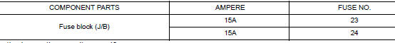
Is the inspection result normal? YES >> GO TO 2.
NO >> Replace the blown fuse after repairing the affected circuit.
2. CHECK REAR WINDOW DEFOGGER POWER SUPPLY CIRCUIT
- Turn ignition switch ON.
- Check voltage between fuse block (J/B) connector and ground
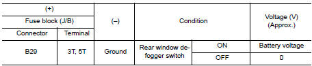
Is the inspection result normal? YES >> GO TO 3.
NO >> Perform rear window defogger relay diagnosis. Refer to DEF-24, "Diagnosis Procedure".
3. CHECK POWER SUPPLY CIRCUIT
- Turn ignition switch ON.
- Check voltage between rear window defogger connector and ground.
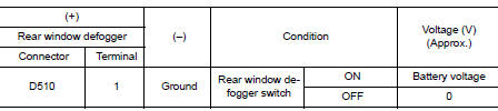
Is the inspection result normal? YES >> GO TO 4.
NO >> GO TO 5.
4. CHECK GROUND CIRCUIT
- Turn ignition switch OFF.
- Disconnect rear window defogger.
- Check continuity between rear window defogger connector and ground.
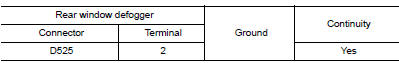
Is the inspection result normal? YES >> GO TO 6.
NO >> Repair or replace harness.
5. CHECK HARNESS CONTINUITY
- Turn ignition switch OFF.
- Disconnect fuse block (J/B).
- Check continuity between fuse block (J/B) connector and rear window defogger condenser connector.
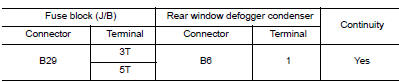
Is the inspection result normal? YES >> Replace rear window defogger condenser. Refer to DEF-41, "Removal and Installation".
NO >> Replace or repair harness.
6. CHECK FILAMENT
Check filament.
Refer to DEF-27, "Component Inspection".
Is the inspection result normal? YES >> Refer to GI-41, "Intermittent Incident".
NO >> Repair filament. Refer to DEF-39, "Inspection and Repair".
Component Inspection
1. CHECK FILAMENT
Check the filament for damage or open circuits.
Refer to DEF-39, "Inspection and Repair".
Is the inspection result normal? YES >> Inspection End.
NO >> Repair filament. Refer to DEF-39, "Inspection and Repair".
 Rear window defogger relay
Description
Power is supplied to the rear window defogger with BCM control.
Component Function Check
1. CHECK REAR WINDOW DEFOGGER RELAY POWER SUPPLY CIRCUIT
Check that an operation noise of rear ...
 Driver side door mirror defogger
Description
Heats the heating wire with the power supply from the rear window defogger
relay to prevent the door mirror
from fogging up.
Component Function Check
1. CHECK DOOR MIRROR DEFOGGER LH ...
Other materials:
Warning/indicator lights and audible reminders
Anti-lock Braking System (ABS)
warning light
Brake warning light
Charge warning light
Low tire pressure warning light
Low windshield washer fluid warning light (if so
equipped)
Master warning light
Power s ...
Power supply and ground circuit
Diagnosis Procedure
Regarding Wiring Diagram information, refer to PCS-24, "Wiring Diagram".
1. CHECK FUSE AND FUSIBLE LINKS
Check that the following IPDM E/R fuse or fusible links are not blown.
Is the fuse blown?
YES >> Replace the blown fuse or fusible link after repairin ...
Front seat
Exploded View
DRIVER POWER SEAT
Headrest
Seatback support
Seatback board
Seatback heater (if equipped)
Seatback trim
Seatback pad
Seat cushion outer finisher (RH)
Seat cushion rear finisher
(RH)
Seat cushion inner finisher (RH)
Seat sli ...
