Nissan Rogue Service Manual: Driver side door mirror defogger
Description
Heats the heating wire with the power supply from the rear window defogger relay to prevent the door mirror from fogging up.
Component Function Check
1. CHECK DOOR MIRROR DEFOGGER LH
Check that heating wire of door mirror defogger LH is heated when turning the rear window defogger switch ON.
Is the inspection result normal? YES >> Door mirror defogger is OK.
NO >> Refer to DEF-28, "Diagnosis Procedure".
Diagnosis Procedure
Regarding Wiring Diagram information, refer to DEF-12, "Wiring Diagram".
1. CHECK POWER SUPPLY CIRCUIT
- Turn ignition switch OFF.
- Disconnect door mirror LH.
- Turn ignition switch ON.
- Check voltage between door mirror LH connector and ground.
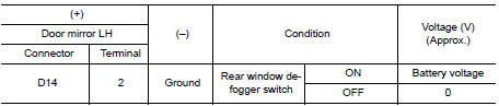
Is the inspection result normal? YES >> GO TO 2.
NO >> Repair or replace harness.
2. CHECK GROUND CIRCUIT
- Turn ignition switch OFF.
- Check continuity between door mirror LH connector and ground.
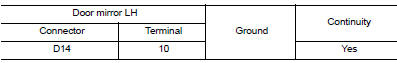
Is the inspection result normal? YES >> GO TO 3.
NO >> Repair or replace harness.
3. CHECK DOOR MIRROR DEFOGGER LH
Check door mirror defogger LH.
Refer to DEF-29, "Component Inspection".
Is the inspection result normal? YES >> GO TO 4.
NO >> Replace door mirror. Refer to MIR-22, "Removal and Installation".
4. CHECK INTERMITTENT INCIDENT
Check intermittent incident.
Refer to GI-41, "Intermittent Incident".
Is the inspection result normal? YES >> Check the following.
- Battery power supply circuit.
- Fuse block (J/B).
NO >> Repair or replace the malfunctioning parts.
Component Inspection
1. CHECK DOOR MIRROR DEFOGGER LH
- Turn ignition switch OFF.
- Disconnect door mirror LH.
- Check continuity between door mirror terminals.
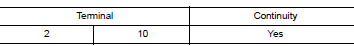
Is the inspection result normal? YES >> Inspection End.
NO >> Replace door mirror LH. Refer to MIR-22, "Removal and Installation".
 Rear window defogger power supply and ground circuit
Description
Heats the heating wire with the power supply from the rear window defogger
relay to prevent the rear window
from fogging up.
Component Function Check
1. CHECK REAR WINDOW DEFOGGER
C ...
 Passenger side door mirror defogger
Description
Heats the heating wire with the power supply from the rear window defogger
relay to prevent the door mirror
from fogging up.
Component Function Check
1.CHECK DOOR MIRROR DEFOGGER RH
...
Other materials:
Rear RH side power window does not operate
WITH BOTH POWER WINDOW MAIN SWITCH AND REAR POWER WINDOW
SWITCH RH
WITH BOTH POWER WINDOW MAIN SWITCH AND REAR POWER WINDOW
SWITCH RH : Diagnosis Procedure
1.CHECK REAR POWER WINDOW SWITCH
Check rear power window switch.
Refer to PWC-36, "Component Function Check".
Is the inspec ...
C1105, C1106, C1107, C1108 wheel sensor
DTC Logic
DTC DETECTION LOGIC
DTC
Display Item
Malfunction detected condition
Possible causes
C1105
RR RH SENSOR-2
When distance between rear wheel sensor RH and
rear wheel sensor RH rotor is large.
When installation of rear whe ...
Front manual seat adjustment
(if so equipped)
Forward and backward
Pull the center of the bar up and hold it while you
slide the seat forward or backward to the desired
position. Release the bar to lock the seat in
position.
Reclining
To recline the seatback, pull the lever up and lean
back. To bring the seatback forward, pull the ...
