Nissan Rogue Service Manual: Component parts
Component Parts Location
- Instrument lower panel LH
|
No. |
Component |
Function |
| 1 | Combination meter |
Refer to MWI-6, "METER SYSTEM : Component Parts Location" for detailed installation location. |
| 2 | TCM |
Refer to TM-12, "CVT CONTROL SYSTEM : Component Parts Location" for detailed installation location. |
| 3 | ECM |
Refer to EC-14, "Component Parts Location" for detailed installation location. |
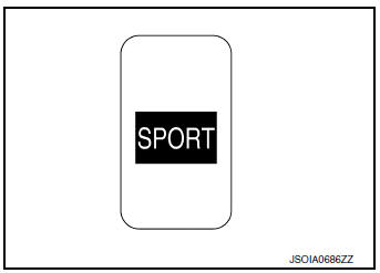
| 4 | SPORT mode switch | Refer to DMS-4, "SPORT Mode Switch". |
SPORT Mode Switch
- The SPORT mode switch is installed to the instrument lower finisher.
- When the SPORT mode indicator lamp on the combination meter is OFF and the SPORT mode switch is pressed, the SPORT mode is active and the SPORT mode indicator lamp is ON.
- When the SPORT mode indicator lamp on the combination meter is ON and the SPORT mode switch is pressed, the SPORT mode is cancelled and the SPORT mode indicator lamp is OFF.
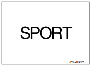
SPORT Mode Indicator Lamp
DESIGN/PURPOSE
The SPORT mode indicator lamp inform the driver that the vehicle is in SPORT mode.
BULB CHECK
Not applicable
SYSTEM DIAGRAM
SIGNAL PATH
- TCM receives SPORT mode switch signal (ON/OFF) from combination
meter via CAN communication.
Based on the signal, TCM transmits SPORT mode signal to ECM via CAN communication.
- ECM transmits SPORT mode indicator signal to combination meter via CAN communication. Based on the signal, combination meter illuminates SPORT mode indicator lamp.
LIGHTING CONDITION
When all of the following conditions are satisfied
- Ignition switch: ON
- The SPORT mode switch is pressed when the SPORT mode indicator lamp is OFF
SHUTOFF CONDITION
When any of the condition listed below is satisfied.
- Ignition switch: Other than ON
- The SPORT mode switch is pressed when the SPORT mode indicator lamp is ON.

 System
SPORT MODE CONTROL
SPORT MODE CONTROL : System Description
SYSTEM DIAGRAM
SYSTEM DISCRIPTION
TCM receives SPORT mode switch signal (ON/OFF) from combination
meter via CAN communica ...
Other materials:
Stall test
Work Procedure
INSPECTION
Check the engine oil level. Replenish if necessary. Refer to LU-7,
"Inspection".
Check for leak of the CVT fluid. Refer to TM-190, "Inspection".
Drive for about 10 minutes to warm up the vehicle so that the CVT
fluid temp ...
Water pump
Exploded View
Cylinder block
Water pump
Water pump gasket
Water pump housing
O-ring
Water pipe
Water pump housing gasket
Refer to INSTALLATION
Removal and Installation
REMOVAL
Drain engine coolant. Refer to CO-8, "Draini ...
Passenger side door mirror defogger
Description
Heats the heating wire with the power supply from the rear window defogger
relay to prevent the door mirror
from fogging up.
Component Function Check
1.CHECK DOOR MIRROR DEFOGGER RH
Check that the heating wire of door mirror defogger RH is heated when turning
the rear window def ...
