Nissan Rogue Service Manual: C1120, C1122, C1124, C1126 ABS in valve system
DTC Logic
DTC DETECTION LOGIC
| DTC | Display Item | Malfunction detected condition | Possible causes |
| C1120 | FR LH IN ABS SOL | When a malfunction is detected in front LH ABS IN valve. |
|
| C1122 | FR RH IN ABS SOL | When a malfunction is detected in front RH ABS IN valve. | |
| C1124 | RR LH IN ABS SOL | When a malfunction is detected in rear LH ABS IN valve. | |
| C1126 | RR RH IN ABS SOL | When a malfunction is detected in rear RH ABS IN valve. |
DTC CONFIRMATION PROCEDURE
1.CHECK SELF-DIAGNOSTIC RESULT
 With CONSULT.
- Turn ignition switch OFF to ON.
- Perform self-diagnostic result.
Is DTC C1120, C1122, C1124 or C1126 detected? YES >> Proceed to diagnosis procedure. Refer to BRC-87, "Diagnosis Procedure".
NO >> Inspection End.
Diagnosis Procedure
Regarding Wiring Diagram information, refer to BRC-57, "Wiring Diagram".
1.CONNECTOR INSPECTION
- Turn ignition switch OFF.
- Disconnect ABS actuator and electric unit (control unit) connectors.
- Check connectors and terminals for deformation, disconnection, looseness or damage.
Is the inspection result normal? YES >> GO TO 2.
NO >> Repair or replace as necessary.
2.CHECK ABS ACTUATOR AND ELECTRIC UNIT (CONTROL UNIT) BATTERY POWER SUPPLY
Check voltage between ABS actuator and electric unit (control unit) connector E125 terminal 25 and ground.

Is the inspection result normal? YES >> GO TO 3.
NO >> Repair or replace malfunctioning components.
3.CHECK ABS ACTUATOR AND ELECTRIC UNIT (CONTROL UNIT) GROUND CIRCUIT
Check continuity between ABS actuator and electric unit (control unit) connector E125 terminals 13, 38 and ground.
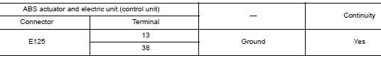
Is the inspection result normal? YES >> Replace ABS actuator and electric unit (control unit). Refer to BRC-136, "Removal and Installation".
NO >> Repair or replace malfunctioning components.
 C1115 ABS sensor [abnormal signal]
DTC Logic
DTC DETECTION LOGIC
DTC
Display Item
Malfunction detected condition
Possible causes
C1115
ABS SENSOR
[ABNORMAL SIGNAL]
When difference in wheel speed betw ...
 C1121, C1123, C1125, C1127 ABS out valve system
DTC Logic
DTC DETECTION LOGIC
DTC
Display Item
Malfunction detected condition
Possible causes
C1121
FR LH OUT ABS SOL
When a malfunction is detected in front LH ABS OU ...
Other materials:
Navigation System voice commands
The following voice commands are available for
the Navigation System:
Street Address (address)
Points of Interest (name)
POI by Category
Home
Address Book
Previous Destinations
Enter Address in Steps
Cancel Route
For additional in ...
CAN system (type 5)
MAIN LINE BETWEEN IPDM-E AND DLC CIRCUIT
Diagnosis Procedure
1.CHECK CONNECTOR
Turn the ignition switch OFF.
Disconnect the battery cable from the negative terminal.
Check the following terminals and connectors for damage, bend and
loose connection (connector side
an ...
Preparation
Special Service Tool
The actual shape of the tools may differ from those tools illustrated here.
Tool number
(TechMate No.)
Tool nam
Description
—
(J-50190)
Signal Tech II
Activate and display TPMS transmitter IDs
Display tire ...
