Nissan Rogue Service Manual: Rear suspension ARM
Exploded View
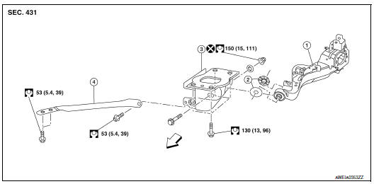
- Rear suspension arm
- Rubber washer (LH/RH)
- Rear suspension arm bracket
- Rear suspension arm stay
 Front
Front
Removal and Installation
REMOVAL
- Remove the wheel hub and bearing. Refer to RAX-16, "Removal and Installation".
- Remove the coil spring. RSU-10, "Removal and Installation - AWD".
- Separate the brake tube and hose from the rear suspension arm. BR-24, "REAR : Exploded View".
- Remove the nut, bolt, rubber washer (LH/RH), and rear suspension arm.
- Inspect the components. Refer to RSU-14, "Inspection".
INSTALLATION
Installation is in the reverse order of removal.
- Align the matching marks made during removal when reusing the disc brake rotor.
- After installation, perform the air bleeding. Refer to BR-16, "Bleeding Brake System".
- Perform final tightening of rear suspension member at its installation position under unladen conditions with tires on level ground.
- Perform the inspection after installation. Refer to RSU-16, "Inspection".
Inspection
INSPECTION AFTER REMOVAL
Visual Inspection
Check rear suspension arm and bushing for deformation, cracks or damage. Replace it if necessary.
INSPECTION AFTER INSTALLATION
- Adjust parking brake operation (stroke). Refer to PB-4, "Inspection and Adjustment".
- Check wheel alignment. Refer to RSU-6, "Inspection".
 Rear shock absorber
Exploded View
Rear suspension member
Upper seat
Coil spring
Lower seat
Rubber washer (LH/RH)
Rear suspension arm
Rear shock absorber
Front
Removal and Installation
REMOVAL ...
 Lower link
Exploded View
Rear suspension member
Lower link
Lower link deflector
Rubber washer (LH/RH)
Rear suspension arm
Front
Removal and Installation
REMOVAL
Remove wheel a ...
Other materials:
AM radio reception
AM signals, because of their low frequency, can
bend around objects and skip along the ground.
In addition, the signals can be bounced off the
ionosphere and bent back to earth. Because of
these characteristics, AM signals are also subject
to interference as they travel from transmitter
to r ...
Service data and specifications (SDS)
General Specification
GENERAL SPECIFICATIONS
( ): Valve timing control “ON”
Drive belt
Spark Plug
Intake Manifold
Exhaust Manifold
Camshaft
*1: Cam wear limit
*2: Total indicator reading
VALVE LIFTER
VALVE CLEARANCE
*: Approximately 80°C (176°F)
AVAIL ...
Preparation
Special Service Tool
The actual shape of the tools may differ from those tools illustrated here.
Tool number
(TechMate No.)
Tool name
Description
—
(J-50190)
Signal Tech II
Activate and display TPMS transmitter IDs
Display tire ...
