Nissan Rogue Service Manual: Lower link
Exploded View
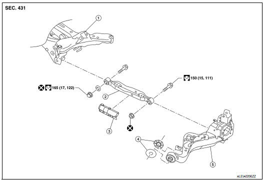
- Rear suspension member
- Lower link
- Lower link deflector
- Rubber washer (LH/RH)
- Rear suspension arm
 Front
Front
Removal and Installation
REMOVAL
- Remove wheel and tire using power tool. Refer to WT-60, "Exploded View".
- Remove connecting rod. Refer to RSU-21, "Exploded View".
- Remove rear height sensor (if equipped). Refer to EXL-271, "Removal and Installation - Rear Height Sensor".
- Set suitable jack under rear suspension arm to relieve the coil spring tension.
- Remove lower link, nut, and bolt from rear suspension arm with power tool.
- Remove lower link, nut, washer, and bolt from rear suspension member with power tool.
- Remove lower link protector (if necessary).
- Perform the inspection after removal. Refer to RSU-17, "Inspection".
INSTALLATION
Installation is in the reverse order of removal.
- Perform final tightening of rear suspension member and axle installation position under unladen conditions with tires on level ground.
- After installation, perform headlamp initialization. Refer to EXL-223, "Diagnosis Procedure".
- Adjust the neutral position of the steering angle sensor. Refer to BRC-70, "Work Procedure".
- Perform the inspection after installation. Refer to RSU-17, "Inspection".
Inspection
INSPECTION AFTER REMOVAL
Check lower link and bushing for any deformation, cracks, or damage. Replace it if necessary.
INSPECTION AFTER INSTALLATION
Check wheel alignment. Refer to RSU-6, "Inspection".
 Rear suspension ARM
Exploded View
Rear suspension arm
Rubber washer (LH/RH)
Rear suspension arm bracket
Rear suspension arm stay
Front
Removal and Installation
REMOVAL
Remove the wheel hu ...
 Upper link
Exploded View
Rear suspension member
Upper link
Rubber washer (LH/RH)
Rear suspension arm
Front
Removal and Installation
REMOVAL
Remove wheel and tir ...
Other materials:
Unit disassembly and assembly
TORQUE CONVERTER AND CONVERTER HOUSING OIL SEAL
Exploded View
Torque converter
O-ring
Converter housing oil seal
Transaxle assembly
: Always replace after every
disassembly.
: Apply CVT fluid
Disassembly
Remove transaxle assembly. Refer to TM-220, "Removal and Instal ...
Basic inspection
INSPECTION AND ADJUSTMENT
ADDITIONAL SERVICE WHEN REPLACING CONTROL UNIT (BCM)
ADDITIONAL SERVICE WHEN REPLACING CONTROL UNIT (BCM) : Description
BEFORE REPLACEMENT
When replacing BCM, save or print current vehicle specification with CONSULT
configuration before replacement.
NOTE:
If “Befo ...
Door outside lower molding
Exploded View
Rear door outside lower molding
Front door outside lower molding
Clip
Front
Removal and Installation
FRONT DOOR OUTSIDE LOWER MOLDING
Removal
Using a suitable tool (A) release clips from front door outside
lower molding (1) starting at the rear and work ...
