Nissan Rogue Service Manual: Rear shock absorber
Exploded View
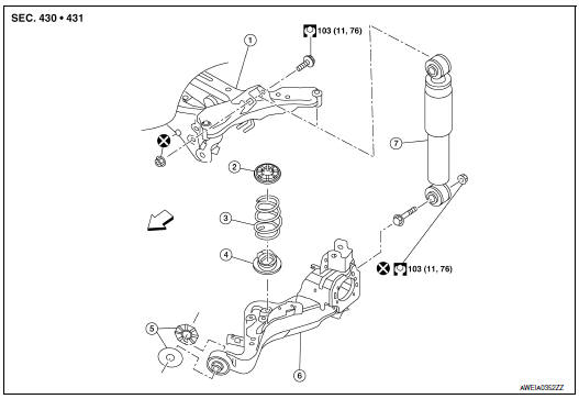
- Rear suspension member
- Upper seat
- Coil spring
- Lower seat
- Rubber washer (LH/RH)
- Rear suspension arm
- Rear shock absorber
 Front
Front
Removal and Installation
REMOVAL
- Support the rear suspension arm using a suitable jack.
CAUTION: Do not damage the rear suspension arm with the suitable jack.
- Remove the lower shock absorber bolt and nut. Separate the shock absorber from the rear suspension arm.
- Remove the upper bolt, nut, and shock absorber.
- Inspect the components. Refer to RSU-5, "Inspection and Adjustment".
INSTALLATION
Installation is in the reverse order of removal.
CAUTION: Do not reuse the lower shock absorber nut.
- Perform the final tightening of nuts and bolts under unladen conditions with tires on level ground.
Inspection
INSPECTION AFTER REMOVAL
- Check shock absorber for deformation, cracks, damage. Replace it if necessary.
- Check welded and sealed areas for oil leaks. Replace it if necessary.
Disposal
- Set shock absorber horizontally to the ground with the piston rod fully extracted.
- Drill 2 – 3 mm (0.08 – 0.12 in) hole at the position (
 ) from top
as shown in the figure to release gas gradually.
) from top
as shown in the figure to release gas gradually.
CAUTION:
- Wear eye protection (safety glasses).
- Wear gloves.
- Be careful with metal chips or oil blown out by the compressed gas.
NOTE:
- Drill vertically in this direction (
 ) directly into the outer tube
avoiding brackets.
) directly into the outer tube
avoiding brackets. - The gas is clear, colorless, odorless, and harmless.
A: 20 – 30 mm (0.79 – 1.18 in)
- Position the drilled hole downward and drain oil by moving the piston rod several times.
CAUTION: Dispose of drained oil according to the law and local regulations.
 Coil spring
Exploded View
Upper seat
Coil spring
Lower seat
Rubber washer (LH/RH)
Rear suspension arm
Front
Removal and Installation - FWD
REMOVAL
Remove the rear wh ...
 Rear suspension ARM
Exploded View
Rear suspension arm
Rubber washer (LH/RH)
Rear suspension arm bracket
Rear suspension arm stay
Front
Removal and Installation
REMOVAL
Remove the wheel hu ...
Other materials:
Rear disc brake
BRAKE PAD
BRAKE PAD : Inspection
INSPECTION
Check brake pad wear thickness from an inspection hole (A) on cylinder
body. Check using a scale if necessary.
Wear thickness : Refer to BR-55, "Rear Disc Brake".
DISC BRAKE ROTOR
DISC BRAKE ROTOR : Inspection
Appearance
Check surfac ...
Preparation
Special Service Tools
The actual shape of the tools may differ from those illustrated here.
Tool number
(Kent-Moore No.)
Tool name
Description
(J-44321)
Fuel pressure gauge
kit
Checks fuel pressure
KV10120000
Fuel tube adapter
...
Steering gear and linkage
Exploded View
REMOVAL AND INSTALLATION
Cotter pin
Steering gear
Heat shiel
Removal and Installation
REMOVAL
Set the front wheels and tires to the straight-ahead position.
Remove the floor cover. Refer to ST-12, "Exploded View".
Remov ...
