
Nissan Rogue Service Manual: Periodic maintenance
IDLE SPEED
Inspection
1.CHECK IDLE SPEED
 With CONSULT
Check idle speed in “DATA MONITOR� mode of “ENGINE� using CONSULT.
 With GST
Check idle speed with Service $01 of GST.
>> INSPECTION END
IGNITION TIMING
Inspection
1.CHECK IGNITION TIMING
- Attach timing light (A) to the ignition coil No.1 harness 1.
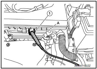
- Check ignition timing.
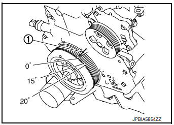
1: Timing indicator
>> INSPECTION END
EVAPORATIVE EMISSION SYSTEM
Inspection
EVAP CANISTER
1.CHECK EVAP CANISTER
- Block port (B).
- Blow air into port (A) and check that it flows freely out of port (C).
- Release blocked port (B).
- Apply vacuum pressure to port (B) and check that vacuum pressure exists at the ports (A) and (C).
- Block port (A) and (B).
- Apply pressure to port (C) and check that there is no leakage.

>> INSPECTION END
EVAP LEAK CHECK
Inspection
CAUTION:
- Do not use compressed air or a high pressure pump.
- Do not exceed 4.12 kPa (0.042 kg/cm2, 0.6 psi) of pressure in EVAP system.
NOTE:
- Do not start engine.
- Improper installation of EVAP service port adapter [commercial service tool: (J-41413-OBD)] to the EVAP service port may cause a leak.
1.EVAP LEAK CHECK
 With CONSULT
- Install EVAP service port adapter [commercial service tool: (J- 41413-OBD)] and pressure pump to EVAP service port.

- Turn ignition switch ON.
- Select the “EVAP SYSTEM CLOSE� in “WORK SUPPORT� mode of “ENGINE� using CONSULT.
- Touch “START�. A bar graph (Pressure indicating display) will appear on the screen.
- Apply positive pressure to the EVAP system until the pressure indicator reaches the middle of the bar graph.
- Remove EVAP service port adapter [commercial service tool: (J-41413-OBD)] and hose with pressure pump.
- Locate the leak using a leak detector [commercial service tool: (J-41416)]. Refer to EC-53, "EVAPORATIVE EMISSION SYSTEM : System Description".

 Without CONSULT
- Install EVAP service port adapter [commercial service tool: (J- 41413-OBD)] and pressure pump to EVAP service port.

- Apply battery voltage between the terminals of EVAP canister vent control valve to make a closed EVAP system.
- To locate the leak, deliver positive pressure to the EVAP system until pressure gauge points reach 1.38 to 2.76 kPa (0.014 to 0.028 kg/cm2, 0.2 to 0.4 psi).
- Remove EVAP service port adapter [commercial service tool: (J-41413-OBD)] and hose with pressure pump.
- Locate the leak using a leak detector [commercial service tool: (J-41416)]. Refer to EC-53, "EVAPORATIVE EMISSION SYSTEM : System Description".

>> INSPECTION END
POSITIVE CRANKCASE VENTILATION
Inspection
1.CHECK PCV VALVE
With engine running at idle, remove PCV valve from rocker cover. A properly working valve makes a hissing noise as air passes through it. A strong vacuum should be felt immediately when a finger is placed over valve inlet.
Is the inspection result normal? YES >> INSPECTION END
NO >> Replace PCV valve. Refer to EC-14, "Component Parts Location".

 Normal operating condition
Description
FUEL CUT CONTROL (AT NO LOAD AND HIGH ENGINE SPEED)
If the engine speed is above 1,800 rpm under no load (for example, the
selector lever position is neutral and
engine speed is over ...
 Removal and installation
ECM
Removal and Installation
EXPLODED VIEW
1 ECM bracket
2 ECM
: Vehicle front
CAUTION:
Perform ADDITIONAL SERVICE WHEN REPLACING ECM. Refer to EC-136, "Work
Procedure".
REMO ...
Other materials:
Door switch
WITH INTELLIGENT KEY
WITH INTELLIGENT KEY : Component Function Check
1.CHECK FUNCTION
Select "DOOR LOCK" of "BCM" using CONSULT.
Select "DOOR SW-DR", "DOOR SW-AS", "DOOR SW-RL", "DOOR SW-RR", in "Data
Monitor&quo ...
Retained power operation does not operate properly
Diagnosis Procedure
1.CHECK FRONT DOOR SWITCH
Check (LH and RH) front door switches.
Refer to DLK-24, "Front Door Switch".
Is the inspection result normal?
YES >> GO TO 2.
NO >> Repair or replace the malfunctioning parts.
2.CONFIRM THE OPERATION
Confirm the operat ...
S connector circuit
Description
The starter motor magnetic switch is supplied with power when the ignition
switch is turned to the START position
while the selector lever is in the P (Park) or N (Neutral) position.
Diagnosis Procedure
Regarding Wiring Diagram information, refer to STR-7, "Wiring Diagram" ...
