Nissan Rogue Service Manual: Body construction
Body Construction

- Outer body side
- Outer front pillar reinforcement
- Upper inner front pillar
- Rear hoodledge reinforcement
- Side dash
- Inner front pillar reinforcement
- Lower front pillar hinge brace
- Upper hinge plate
- Weld nut
- Upper dash
- Upper steering member bracket
- Lower dash
- Lower hinge plate
- Side dash reinforcement
- Outer sill reinforcement
- Inner sill
- Lower front pillar reinforcement
- Front outrigger
- Front floor
- Outer sill brace
- 2nd crossmember
- 2nd crossmember reinforcement
- Center pillar hinge brace
- Center pillar reinforcement
- Inner center pillar
- Lower center pillar hinge brace
- Seat belt anchor
- Inner sill extension
- Rear seat crossmember
- Rear floor front extension
- Rear side member
- Inner rear pillar reinforcement
- Rear pillar seat belt anchor
- Inner rear pillar
- Back pillar main
- Back door stay reinforcement
- Upper back pillar reinforcement
- Rear roof rail brace
- Outer rear wheelhouse
- Inner rear wheelhouse
Rear Fender Hemming Process
- A wheel arch is to be installed and hemmed over the left and right outer wheel houses.
- In order to hem the wheel arch, it is necessary to repair any damaged or defaced parts around outer wheel house.
CAUTION: Ensure that the area that is to be glued around the outer wheelhouse is undamaged or defaced.
PROCEDURE OF THE HEMMING PROCESS
- Peel off old bonding material on the surface of the outer wheelhouse and clean thoroughly.
- Peel off a primer coat in the specified area where new adhesive is to be applied on rear fender (the replacing part).
- Apply new adhesive to both specified areas of the outer wheelhouse and rear fender.
<Adhesive> 3M™ Automix™ Panel Bonding Adhesive 08115 or equivalent
- Attach rear fender to the body of the car, and weld the required part except the hemming part.

- Bend the welded part starting from the center of the wheel arch gradually with a hammer and a dolly. (Also hem the end of the flange.)
- Hemming with a hammer is conducted to an approximate angle of 80 degrees.
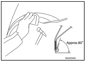
- Starting from the center, hem the wheel arch gradually, using slight back and forth motion with a hemming tool.
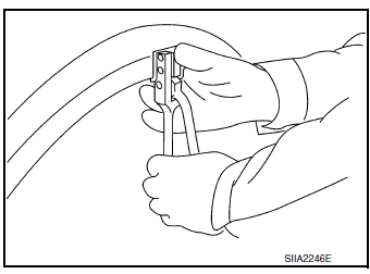
- Seal up the area around the hemmed end of the flange.

 Corrosion protection
Description
To provide improved corrosion prevention, the following anti-corrosive
measures have been implemented in
NISSAN production plants. When repairing or replacing body panels, it is
nece ...
 Replacement operations
Description
This section is prepared for technicians who have attained a high level
of skill and experience in repairing
collision-damaged vehicles and also use modern service tools and equip ...
Other materials:
Disassembly and assembly
FUEL LEVEL SENSOR UNIT
Exploded View
Fuel Level Sensor Unit
Fuel filter and pump assembly
Fuel level sensor unit
Float arm assembly
Fuel tank temperature sensor
Disassembly and Assembly
NOTE:
Fuel level sensor unit and fuel tank temperature sensor are replaced as and
assembl ...
P0850 PNP switch
Description
Transmission range switch is turn ON when the selector lever is P or N.
ECM detects the position because the continuity of the line (the ON) exists.
DTC Description
DTC DETECTION LOGIC
DTC No.
CONSULT screen terms
(Trouble diagnosis content)
DTC detecting condition ...
U1000 CAN COMM CIRCUIT
Description
CAN communication allows a high rate of information transmission through the
two communication lines
(CAN-H line and CAN-L line) connecting various control units in the system. Each
control unit transmits/
receives data but selectively reads required data only.
DTC Logic
DTC DET ...
