Nissan Rogue Service Manual: Parking brake front cable
Removal and Installation
REMOVAL
- Remove the instrument lower panel LH. Refer to IP-22, "Removal and Installation".
- Remove driver seat (LH). Refer to SE-32, "DRIVER SIDE : Removal and Installation"
- Remove the center console. Refer to IP-18, "Removal and Installation".
- Remove the parking brake control. Refer to PB-7, "Removal and Installation"
- Remove front door welts (LH). Refer to INT-23, "BODY SIDE WELT : Removal and Installation - Front Door Welt".
- Remove dash side finisher (LH). Refer to INT-24, "DASH SIDE FINISHER : Removal and Installation".
- Remove shift selector. Refer to TM-194, "Removal and Installation".
- Remove the front floor connecting ducts (LH/RH). Refer to VTL-10, "FRONT FLOOR DUCT : Removal and Installation - Front Floor Connecting Duct".
- Remove the front floor duct. Refer to VTL-11, "FRONT FLOOR DUCT : Removal and Installation - Front Floor Duct"
- Remove the rear center ventilator duct. Refer to VTL-11, "REAR CENTER VENTILATOR DUCT : Removal and Installation".
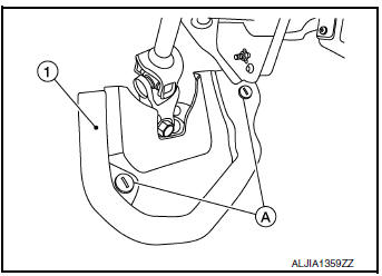
- Release clips (A) using a suitable tool and remove steering joint floor cover (1).
- Place front floor trim aside and remove the front floor spacer. Refer to INT-26, "Exploded View".
- Remove the bolts from the parking brake front cable mount. Refer to PB-7, "Exploded View".
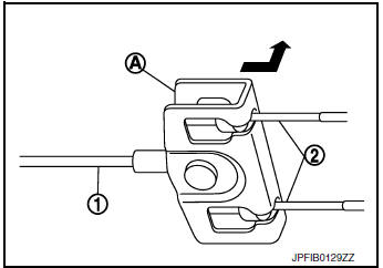
- Pull equalizer (A) of the parking brake front cable (1) in a
rearward
direction and then push upward to separate each parking
brake rear cable (2) from the parking brake front cable (1).
CAUTION: To prevent damage to the parts, do not bend the parking brake cables.
- Remove the parking brake front cable.
INSTALLATION
Installation is in the reverse order of removal.
CAUTION: Do not reuse the adjusting nut.
- Inspect and adjust the parking brake pedal. Refer to PB-4, "Inspection and Adjustment".
 Parking brake control
Exploded View
Parking brake rear cable (RH)
Parking brake rear cable (LH)
Parking brake front cable
Parking brake control
Adjusting nut
Parking brake switch
Removal and ...
 Parking brake rear cable
Removal and Installation
REMOVAL
Remove the center console assembly. Refer to IP-18, "Removal and
Installation".
Remove shift selector. Refer to TM-194, "Removal a ...
Other materials:
P0962 pressure control solenoid A
DTC Description
DTC DETECTION LOGIC
DTC
CONSULT screen terms
(Trouble diagnosis content)
DTC detection condition
P0962
PC SOLENOID A
(Pressure Control Solenoid A Control Circuit
Low)
When all of the following conditions are satisfied and this state is
maint ...
Active engine brake
The Active Engine Brake function adds subtle
deceleration by controlling CVT gear ratio, depending
on the cornering condition calculated
from driverŌĆÖs steering input and plural sensors.
This benefit is for easier traceability and less
workload of adjusting speed with braking at corners.
...
Power switch illumination circuit
Description
Provides the power supply and the ground to control the power switch
illumination.
Component Function Check
1.CHECK POWER SWITCH ILLUMINATION OPERATION
CONSULT ACTIVE TEST
Turn the power switch ON.
Select ŌĆ£ENGINE SW ILLUMIŌĆØ of ŌĆ£BCMŌĆØ active test item.
&n ...
