Nissan Rogue Service Manual: P2814 select solenoid
DTC Description
DTC DETECTION LOGIC
| DTC | CONSULT screen terms (Trouble diagnosis content) | DTC detection condition |
| P2814 | SELECT SOLENOID (Select solenoid) | When all of the following conditions are satisfied and this state is
maintained
for 0.48 seconds:
|
POSSIBLE CAUSE
- Harness or connector (Select solenoid valve circuit shorted to ground)
- Select solenoid valve
FAIL-SAFE
Selector shock is large
DTC CONFIRMATION PROCEDURE
CAUTION: Be careful of the driving speed.
1.PREPARATION BEFORE WORK
If another "DTC CONFIRMATION PROCEDURE" occurs just before, turn ignition switch OFF and wait for at least 10 seconds, then perform the next test.
>> GO TO 2.
2.CHECK DTC DETECTION
- Start the engine.
- Maintain the following conditions. (Keep 5 seconds or more after the selector lever shifted.)
Selector lever : N → D, N → R, P → R
- Check the first trip DTC.
Is “P2814” detected? YES >> Go to TM-172, "Diagnosis Procedure".
NO-1 >> To check malfunction symptom before repair: Refer to GI-41, "Intermittent Incident".
NO-2 >> Confirmation after repair: INSPECTION END
Diagnosis Procedure
1.CHECK CIRCUIT BETWEEN TCM AND CVT UNIT
- Turn ignition switch OFF.
- Disconnect TCM connector and CVT unit connector.
- Check continuity between TCM harness connector terminal and ground.

Is the inspection result normal? YES >> GO TO 2.
NO >> Repair or replace damaged parts.
2.CHECK CIRCUIT BETWEEN CVT UNIT AND GROUND
Check continuity between CVT unit harness connector terminal and ground.
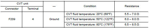
Is the inspection result normal? YES >> INSPECTION END
NO >> There is malfunction of select solenoid valve. Replace transaxle assembly. Refer to TM-220, "Removal and Installation".
 P2813 select solenoid
DTC Description
DTC DETECTION LOGIC
DTC
CONSULT screen terms
(Trouble diagnosis content)
DTC detection condition
P2813
SELECT SOLENOID
(Select solenoid)
When any of ...
 P2815 select solenoid
DTC Description
DTC DETECTION LOGIC
DTC
CONSULT screen terms
(Trouble diagnosis content)
DTC detection condition
P2815
SELECT SOLENOID
(Select solenoid)
When all of ...
Other materials:
Low tire pressure warning lamp blinks
Description
The low tire pressure warning lamp blinks when the power switch is turned ON.
NOTE:
The position of an inactive tire pressure sensor can be identified by checking
the blinking timing of the low tire
pressure warning lamp.
Diagnosis Procedure
1.TIRE PRESSURE SENSOR ID REGISTRA ...
General maintenance
During the normal day-to-day operation of the
vehicle, general maintenance should be performed
regularly as prescribed in this section. If
you detect any unusual sounds, vibrations or
smells, be sure to check for the cause or have a
NISSAN dealer do it promptly. In addition, you
should notify ...
DTC/Circuit diagnosis
C1201 AWD CONTROL UNIT
DTC Description
DTC DETECTION LOGIC
DTC No.
CONSULT screen terms
(Trouble diagnosis content)
DTC detecting condition
C1201
CONTROLLER FAILURE
(Control unit failure)
Malfunction has occurred inside AWD control unit.
POSSIBLE CAUSE
Int ...
