Nissan Rogue Service Manual: P2127, P2128 APP sensor
DTC Description
DTC DETECTION LOGIC
| DTC No. | CONSULT screen terms (Trouble diagnosis content) | DTC detecting condition |
| P2127 | APP SEN 2/CIRC (Throttle/pedal position sensor/switch ″E″ circuit low) | An excessively low voltage from the APP sensor 2 is sent to ECM. |
| P2128 | APP SEN 2/CIRC (Throttle/pedal position sensor/switch ″E″ circuit high) | An excessively high voltage from the APP sensor 2 is sent to ECM. |
POSSIBLE CAUSE
- Harness or connectors (APP sensor 2 circuit is open or shorted.)
- Accelerator pedal position sensor (APP sensor 2)
- Sensor power supply 2 circuit
FAIL-SAFE
- The ECM controls the electric throttle control actuator in regulating the throttle opening in order for the idle position to be within +10 degrees.
- The ECM regulates the opening speed of the throttle valve to be slower than the normal condition. So, the acceleration will be poor.
DTC CONFIRMATION PROCEDURE
1.PRECONDITIONING
If DTC Confirmation Procedure has been previously conducted, always perform the following procedure before conducting the next test.
- Turn ignition switch OFF and wait at least 10 seconds.
- Turn ignition switch ON.
- Turn ignition switch OFF and wait at least 10 seconds.
TESTING CONDITION: Before performing the following procedure, confirm that battery voltage is more than 8 V at idle.
>> GO TO 2.
2.PERFORM DTC CONFIRMATION PROCEDURE
- Start engine and let it idle for 1 second.
- Check DTC.
Is DTC detected? YES >> Proceed to EC-443, "Diagnosis Procedure".
NO >> INSPECTION END
Diagnosis Procedure
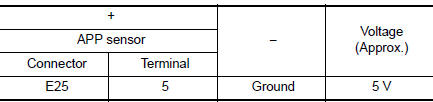
1.CHECK APP SENSOR 2 POWER SUPPLY
- Turn ignition switch OFF.
- Disconnect accelerator pedal position (APP) sensor harness connector.
- Turn ignition switch ON.
- Check the voltage between APP sensor harness connector and ground.
Is the inspection result normal? YES >> GO TO 3.
NO >> GO TO 2.
2.CHECK SENSOR POWER SUPPLY 2 CIRCUIT
Perform EC-484, "Diagnosis Procedure".
Is inspection result normal? YES >> Perform the trouble diagnosis for power supply circuit.
NO >> Repair or replace error-detected parts.
3.CHECK APP SENSOR 2 GROUND CIRCUIT
- Turn ignition switch OFF.
- Disconnect ECM harness connector.
- Check the continuity between APP sensor harness connector and ECM harness connector.
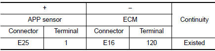
- Also check harness for short to power.
Is the inspection result normal? YES >> GO TO 4.
NO >> Repair or replace error-detected parts.
4.CHECK APP SENSOR 2 INPUT SIGNAL CIRCUIT
- Check the continuity between APP sensor harness connector and ECM harness connector.
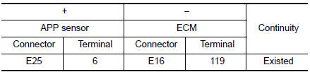
- Also check harness for short to ground and to power.
Is the inspection result normal? YES >> GO TO 5.
NO >> Repair or replace error-detected parts
5.CHECK APP SENSOR
Check the APP sensor. Refer to EC-444, "Component Inspection".
Is the inspection result normal? YES >> GO TO 6.
NO >> Replace accelerator pedal assembly. Refer to ACC-3, "Removal and Installation".
6.CHECK INTERMITTENT INCIDENT
Refer to GI-41, "Intermittent Incident".
>> INSPECTION END
Component Inspection
1.CHECK ACCELERATOR PEDAL POSITION SENSOR
- Turn ignition switch OFF.
- Reconnect all harness connectors disconnected.
- Turn ignition switch ON.
- Check the voltage between ECM harness connector terminals as per the following cond
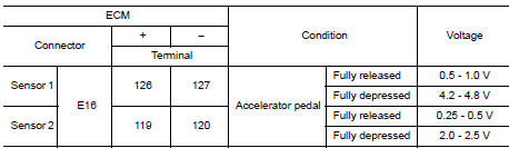
Is the inspection result normal? YES >> INSPECTION END
NO >> Replace accelerator pedal assembly. Refer to ACC-3, "Removal and Installation".
 P2122, P2123 APP sensor
DTC Description
DTC DETECTION LOGIC
DTC No.
CONSULT screen terms
(Trouble diagnosis content)
DTC detecting condition
P2122
APP SEN 1/CIRC
(Throttle/pedal position sens ...
 P2135 TP sensor
DTC Description
DTC DETECTION LOGIC
DTC No.
CONSULT screen terms
(Trouble diagnosis content)
DTC detecting condition
P2135
TP SENSOR-B1
(Throttle/pedal position sensor ...
Other materials:
P1574 ASCD vehicle speed sensor
Description
The ECM receives two vehicle speed sensor signals via CAN communication line.
One is sent from combination
meter, and the other is from TCM (Transmission control module). The ECM uses
these signals for ASCD
control. Refer to EC-47, "AUTOMATIC SPEED CONTROL DEVICE (ASCD) : Sys ...
USB (Universal Serial Bus) Connection Port (models with Navigation System)
(if so equipped)
USB (Universal Serial Bus) Connection Port (models with Navigation System)
Connecting a device to the USB
Connection Port
WARNINGDo not connect, disconnect, or operate the
USB device while driving. Doing so can be
a distraction. If distracted you could lose
control of your ...
Moonroof does not operate properly
Diagnosis Procedure
1. CHECK BCM POWER SUPPLY AND GROUND CIRCUIT
Check BCM power supply and ground circuit.
Refer to BCS-68, "Diagnosis Procedure" (with Intelligent Key System), BCS-128,
"Diagnosis Procedure" (without
Intelligent Key System)
Is the inspection result norm ...
