Nissan Rogue Service Manual: Cooling fan
Exploded View
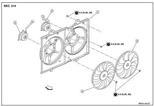
- Fan shroud
- Fan motor (LH)
- Fan motor (RH)
- Cooling fan (RH)
- Cooling fan (LH)
 Front
Front
Removal and Installation
REMOVAL
WARNING: Do not remove the radiator cap when the engine is hot. Serious burns could occur from high pressure engine coolant escaping from the radiator. Wrap a thick cloth around the cap. Slowly turn it a quarter turn to allow built-up pressure to escape. Carefully remove the cap by turning it all the way.
NOTE: When removing components such as hoses, tubes/lines, etc., cap or plug openings to prevent fluid from spilling.
- Disconnect battery negative terminal.
- Disconnect battery positive terminal. Refer to PG-77, "Exploded View".
- Depower SRS system. Refer to SR-2, "Service".
- Drain engine coolant from radiator. Refer to CO-8, "Draining".
CAUTION:
- Perform this step when the engine is cold.
- Do not spill engine coolant on the drive belt.
- Remove engine under cover. Refer to EXT-37, "ENGINE UNDER COVER : Removal and Installation".
- Remove front air spoiler. Refer to EXT-16, "Exploded View".
- Remove fender protector side cover. Refer to EXT-28, "FENDER PROTECTOR : Exploded View".
- Remove air duct (inlet). Refer to EM-24, "Exploded View".
- Remove bumper fascia assembly. Refer to EXT-16, "Exploded View".
- Remove radiator core support (upper). Refer to XX.
- Remove radiator hose (upper) from radiator. Refer to CO-13, "Exploded
View".
CAUTION: Do not spill engine coolant on the drive belt.
- Disconnect harness connector from cooling fan controller.
- Remove harness retainers from fan shroud.
- Remove CVT cooler hose retainers from fan shroud.
- Remove reservoir tank hose from fan shroud. Refer to CO-13, "Exploded View".
- Remove fan shroud. Refer to CO-17, "Exploded View".
CAUTION: Be careful not to damage the radiator.
INSTALLATION
Installation is in the reverse order of removal.
CAUTION: Do not spill engine coolant in the engine compartment. Use a shop cloth to absorb engine coolant.
NOTE: Cooling fan is controlled by ECM. For details, refer to EC-64, "On Board Diagnosis Function".
Disassembly and Assembly
DISASSEMBLY
- Remove cooling fan mounting nuts, and then remove the cooling fans (RH and LH).
- Remove fan motor cover and fan motors (RH and LH).
ASSEMBLY
Assembly is in the reverse order of disassembly.
CAUTION: Apply high thread locking sealant to cooling fan motor shaft.
Inspection
INSPECTION AFTER DISASSEMBLY
Cooling Fan
Inspect cooling fan for cracks or unusual bends.
- If anything is found, replace cooling fan.
 Radiator
Exploded View
REMOVAL
Reservoir tank
Reservoir tank cap
Reservoir tank hose
Mounting rubber (upper)
Radiator cap
Radiator
CVT fluid cooler hose
...
 Water pump
Exploded View
Cylinder block
Water pump
Water pump gasket
Water pump housing
O-ring
Water pipe
Water pump housing gasket
Refer to INSTALLAT ...
Other materials:
Symptom diagnosis
SQUEAK AND RATTLE TROUBLE DIAGNOSES
Work Flow
CUSTOMER INTERVIEW
Interview the customer if possible, to determine the conditions that exist
when the noise occurs. Use the Diagnostic
Worksheet during the interview to document the facts and conditions when the
noise occurs and any
custome ...
P0963 pressure control solenoid A
DTC Description
DTC DETECTION LOGIC
DTC
CONSULT screen terms
(Trouble diagnosis content)
DTC detection condition
P0963
PC SOLENOID A(Pressure Control Solenoid A Control Circuit
High)
When all of the following conditions are satisfied and this state is
maintain ...
Replacement operations
Description
This section is prepared for technicians who have attained a high level
of skill and experience in repairing
collision-damaged vehicles and also use modern service tools and equipment.
Persons unfamiliar with body
repair techniques should not attempt to repair collision-dam ...
