
Nissan Rogue Service Manual: P0117, P0118 ECT sensor
DTC Description
DTC DETECTION LOGIC
| DTC No. | CONSULT screen terms (Trouble diagnosis content) | DTC detecting condition |
| P0117 | ECT SEN/CIRC (Engine coolant temperature sensor 1 circuit low) | An excessively low voltage from the engine coolant temperature sensor is sent to ECM. |
| P0118 | ECT SEN/CIRC (Engine coolant temperature sensor 1 circuit high) | An excessively high voltage from the engine coolant temperature sensor is sent to ECM. |
POSSIBLE CAUSE
- Harness or connectors (Engine coolant temperature sensor circuit is open or shorted.)
- Engine coolant temperature sensor
FAIL-SAFE
Not applicable
DTC CONFIRMATION PROCEDURE
1.PRECONDITIONING
If DTC Confirmation Procedure has been previously conducted, always perform the following procedure before conducting the next test.
- Turn ignition switch OFF and wait at least 10 seconds.
- Turn ignition switch ON.
- Turn ignition switch OFF and wait at least 10 seconds.
>> GO TO 2.
2.PERFORM DTC CONFIRMATION PROCEDURE
- Turn ignition switch ON and wait at least 5 seconds.
- Check DTC.
Is DTC detected? YES >> Proceed to EC-213, "Diagnosis Procedure".
NO >> INSPECTION END
Diagnosis Procedure
1.CHECK ENGINE COOLANT TEMPERATURE SENSOR POWER SUPPLY
- Turn ignition switch OFF.
- Disconnect engine coolant temperature (ECT) sensor harness connector.
- Turn ignition switch ON.
- Check the voltage between ECT sensor harness connector and ground.
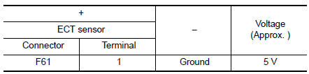
Is the inspection result normal? YES >> GO TO 3.
NO >> GO TO 2.
2.CHECK ENGINE COOLANT TEMPERATURE SENSOR POWER SUPPLY CIRCUIT
- Turn ignition switch OFF.
- Disconnect ECM harness connector.
- Check the continuity between ECT sensor harness connector and ECM harness connector.

- Also check harness for short to ground.
Is the inspection result normal? YES >> Perform the trouble diagnosis for power supply circuit.
NO >> Repair or replace error-detected parts.
3.CHECK ENGINE COOLANT TEMPERATURE SENSOR GROUND CIRCUIT
- Turn ignition switch OFF.
- Disconnect ECM harness connector.
- Check the continuity between ECT sensor harness connector and ECM harness connector.
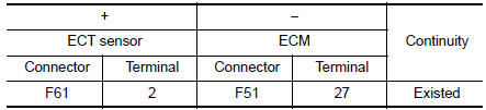
- Also check harness for short to ground to power.
Is the inspection result normal? YES >> GO TO 4.
NO >> Repair or replace error-detected parts.
4.CHECK ENGINE COOLANT TEMPERATURE SENSOR
Check the engine coolant temperature sensor. Refer to EC-212, "Component Inspection".
Is the inspection result normal? YES >> GO TO 5.
NO >> Replace engine coolant temperature sensor. Refer to CO-23, "Exploded View".
5.CHECK INTERMITTENT INCIDENT
Refer to GI-41, "Intermittent Incident".
>> INSPECTION END
Component Inspection
1.CHECK ENGINE COOLANT TEMPERATURE (ECT) SENSOR
- Turn ignition switch OFF.
- Disconnect ECT sensor harness connector.
- Remove ECT sensor.
- Check resistance between ect sensor terminals by heating with hot water as shown in the figure.
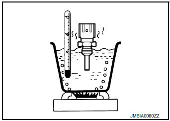
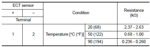
Is the inspection result normal?
YES >> INSPECTION END
NO >> Replace engine coolant temperature sensor. Refer to CO-23, "Exploded View".
 P0116 ECT sensor
DTC Description
DTC DETECTION LOGIC
DTC No.
CONSULT screen terms
(Trouble diagnosis content)
DTC detecting condition
P0116
ECT SENSOR
(Engine coolant temperature senso ...
 P0122, P0123 TP sensor
DTC Description
DTC DETECTION LOGIC
DTC No.
CONSULT screen terms
(Trouble diagnosis content)
DTC detecting condition
P0122
TP SEN 2/CIRC-B1
(Throttle/pedal position se ...
Other materials:
Preparation
Special Service Tool
The actual shape of the tools may differ from those illustrated here.
Tool number
(TechMate No.)
Tool name
Description
—
(J-46534)
Trim Tool Set
Removing trim components
...
Manual control
While using the Voice Recognition system, it is
possible to select menu options by using the
steering wheel controls instead of speaking voice
commands. To activate manual control mode,
press the PHONE/SEND ( ) button on
the
steering wheel to access the phone menu and
then press either u ...
Fluid cooler hose
Exploded View
COMPONENT PARTS LOCATION
Transaxle assembly
Fluid cooler hose A
Hose clamp
Fluid cooler hose B
CVT oil warmer
To radiator
: Always replace after every
disassembly.
Removal and Installation
REMOVAL
NOTE:
When removing components such as hoses, tubes/lines, ...
