Nissan Rogue Service Manual: Front door finisher
Exploded View
- Front door
- Front door pull handle bracket
- Front door pull handle
- Front power window switch (RH) finisher
- Front door inside handle finisher
- Front door finisher
 Clip
Clip
 Pawl
Pawl
REMOVAL
NOTE: LH shown, RH similar.
- Release pawls using a suitable tool (A) from front of inside handle finisher (1) while working toward the rear and remove.
: Pawl
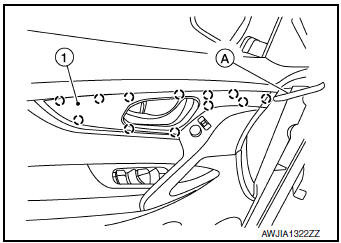
- Release pawls using a suitable tool (A) from front of inside handle finisher (1) while working toward the rear and remove.
: Pawl
- Disconnect harness connector from door mirror remote control switch (LH only).
- Remove bolts (A) and front door inside pull handle bracket (1).

- Release pawls using a suitable tool (A) and remove front door power window and door lock/unlock switch finisher (1).
- Disconnect harness connectors from front door power window and door lock/unlock switch.
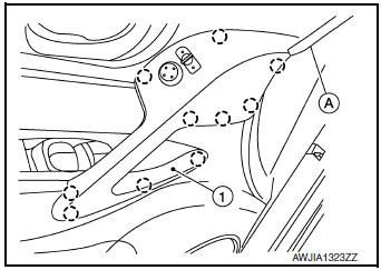
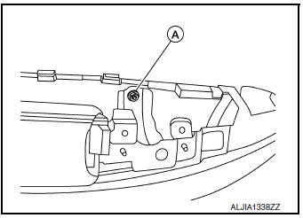
- Remove front door finisher bolt (A).
- Insert suitable tool (A) between front door finisher and door panel to release clips and pawl, starting from the bottom and working to the top.
 : Clip

INSTALLATION
Installation is in the reverse order of removal.
CAUTION:
- Visually check the clips and pawls for deformation and damage during installation. Replace with new ones if necessary.
- When installing front door finisher, check that clips and pawls are securely placed in door panel holes.
NOTE: When main power window and door lock/unlock switch or power window door lock/unlock switch RH is removed or replaced, it is necessary to perform the initialization procedure. Refer to PWC-25, "Work Flow".

 Rear door finisher
Exploded View
Rear door
Rear power window switch finisher
Rear door screw cover
Rear door inside handle finisher
Rear door finisher
Tether clip
Tether ...
Other materials:
Vehicle Dynamic Control (VDC) system
The Vehicle Dynamic Control (VDC) system uses
various sensors to monitor driver inputs and vehicle
motion. Under certain driving conditions,
the VDC System helps to perform the following
functions:
Controls brake pressure to reduce wheel
slip on 1 slipping drive wheel so power is
t ...
Moonroof switch
Removal and Installation
REMOVAL
Remove map lamp assembly. Refer to INL-55, "Removal and Installation".
Using a suitable tool release clip from harness connector.
: Clip
Using a suitable tool release pawls and remove moonroof switch
finisher (1).
Using a ...
Preparation
PREPARATION
Special Service Tool
The actual shape of the tools may differ from those illustrated here.
Tool number
(TechMate No.)
Tool name
Description
KV40107300
( — )
Boot band crimping tool
Installing boot band
KV40107500
( — )
...
