Nissan Rogue Service Manual: P0116 ECT sensor
DTC Description
DTC DETECTION LOGIC
| DTC No. | CONSULT screen terms (Trouble diagnosis content) | DTC detecting condition |
| P0116 | ECT SENSOR (Engine coolant temperature sensor 1 circuit range/performance) | The comparison result of signals transmitted to ECM from each temperature sensor (IAT sensor, ECT sensor, FTT sensor, and EOT sensor) shows that the voltage signal of the ECT sensor is higher/lower than that of other temperature sensors when the engine is started with its cold state. |
POSSIBLE CAUSE
- Harness or connectors (High or low resistance in the ECT sensor circuit)
- ECT sensor
FAIL-SAFE
Not applicable
DTC CONFIRMATION PROCEDURE
1.INSPECTION START
Is it necessary to erase permanent DTC? YES >> GO TO 3.
NO >> GO TO 2.
2.CHECK ENGINE COOLANT TEMPERATURE (ECT) SENSOR
- Turn ignition switch OFF.
- Disconnect ECT sensor harness connector.
- Remove ECT sensor. Refer to CO-23, "Exploded View".
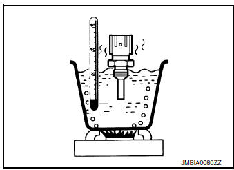
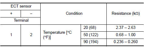
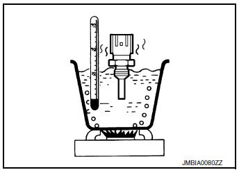
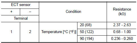
- Check resistance between ECT sensor terminals by heating with hot water as shown in the figure.
Is the inspection result normal? YES >> GO TO 5.
NO >> Proceed to EC-212, "Diagnosis Procedure".
3.PRECONDITIONING
If DTC CONFIRMATION PROCEDURE has been previously conducted, always perform the following procedure before conducting the next test.
- Turn ignition switch OFF and wait at least 10 seconds.
- Turn ignition switch ON.
- Turn ignition switch OFF and wait at least 10 seconds.
TESTING CONDITION:
- Before performing the following procedure, do not add fuel.
- Before performing the following procedure, check that fuel level is between 1/4 and 4/4.
- Before performing the following procedure, confirm that battery voltage is 11 V or more at idle.
4.PERFORM DTC CONFIRMATION PROCEDURE
- Move the vehicle to a cool place.
NOTE: Cool the vehicle in an environment of ambient air temperature between −10┬░C (14┬░F) and 35┬░C (95┬░F).
- Turn ignition switch OFF and leave the vehicle for 12 hours.
CAUTION: Never turn ignition switch ON during this procedure.
NOTE: The vehicle must be cooled with the food open.
- Start engine and let it idle for 5 minutes or more.
CAUTION: Never turn ignition switch OFF during idling.
- Check 1st trip DTC.
Is 1st trip DTC detected? YES >> Proceed to EC-212, "Diagnosis Procedure".
NO >> INSPECTION END
5.CHECK INTERMITTENT INCIDENT
Refer to GI-41, "Intermittent Incident".
>> INSPECTION END
Diagnosis Procedure
1.CHECK ENGINE COOLANT TEMPERATURE (ECT) SENSOR
Check ECT sensor. Refer to EC-212, "Component Inspection".
Is the inspection result normal? YES >> GO TO 2.
NO >> Replace ECT sensor. Refer to CO-23, "Exploded View".
2.CHECK INTERMITTENT INCIDENT
Refer to GI-41, "Intermittent Incident".
>> INSPECTION END
Component Inspection
1.CHECK ENGINE COOLANT TEMPERATURE (ECT) SENSOR
- Turn ignition switch OFF.
- Disconnect ECT sensor harness connector.
- Remove ECT sensor.
- Check resistance between ECT sensor terminals by heating with hot water as shown in the figure.
Is the inspection result normal? YES >> INSPECTION END
NO >> Replace engine coolant temperature sensor. Refer to CO-23, "Exploded View".
 P0112, P0113 IAT sensor
DTC Description
DTC DETECTION LOGIC
DTC No.
CONSULT screen terms
(Trouble diagnosis content)
DTC detecting condition
P0112
IAT SEN/CIRCUIT- B1
(Intake air temperature ...
 P0117, P0118 ECT sensor
DTC Description
DTC DETECTION LOGIC
DTC No.
CONSULT screen terms
(Trouble diagnosis content)
DTC detecting condition
P0117
ECT SEN/CIRC
(Engine coolant temperature sen ...
Other materials:
Power window retained power operation does not operate
properly
Diagnosis Procedure
1.CHECK DOOR SWITCH
Check door switch.
Refer to DLK-149, "Component Function Check" (with Intelligent Key system) or
DLK-319,
"Component Function Check" (without Intelligent Key system).
Is the inspection result normal?
YES >> GO TO 2.
NO ...
Precautions
Precaution for Supplemental Restraint System (SRS) "AIR BAG" and "SEAT
BELT
PRE-TENSIONER"
The Supplemental Restraint System such as ÔÇťAIR BAGÔÇŁ and ÔÇťSEAT BELT
PRE-TENSIONERÔÇŁ, used along
with a front seat belt, helps to reduce the risk or severity of injury to the
...
Trouble diagnosis - specification value
Description
The specification (SP) value indicates the tolerance of the value that is
displayed in ÔÇťSPECÔÇŁ of ÔÇťDATA MONITORÔÇŁ
mode of CONSULT during normal operation of the Engine Control System. When the
value in ÔÇťSPECÔÇŁ of
ÔÇťDATA MONITORÔÇŁ mode is within the SP value, the Engine ...
