Nissan Rogue Service Manual: Overdrive control switch
Component Function Check
1.CHECK O/D OFF INDICATOR LAMP FUNCTION
Check O/D OFF indicator lamp turns ON for approx. 2 seconds when ignition switch turns ON.
Is the inspection results normal? YES >> GO TO 2.
NO >> Go to TM-181, "Diagnosis Procedure".
2.CHECK OVERDRIVE CONTROL SWITCH FUNCTION
- Shift the selector lever to “D” position.
- Check that O/D OFF indicator lamp turns ON/OFF when overdrive control switch is operated.
Is the inspection results normal? YES >> INSPECTION END
NO >> Go to TM-178, "Diagnosis Procedure".
Diagnosis Procedure
1.CHECK OVERDRIVE CONTROL SWITCH CIRCUIT
- Turn ignition switch OFF.
- Disconnect CVT shift selector connector.
- Turn ignition switch ON.
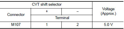
- Check voltage between CVT shift selector harness connector terminals.
Is the inspection result normal? YES >> GO TO 2.
NO >> GO TO 4.
2.CHECK CVT SHIFT SELECTOR CIRCUIT
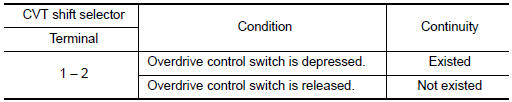
Check continuity between CVT shift selector harness connector terminals.
Is the inspection result normal? YES >> GO TO 7.
NO >> GO TO 3.
3.CHECK OVERDRIVE CONTROL SWITCH
Check overdrive control switch. Refer to TM-179, "Component Inspection".
Is the inspection result normal? YES >> Repair CVT shift selector assembly. Refer to TM-194, "Removal and Installation".
NO >> Replace selector lever knob. Refer to TM-194, "Removal and Installation".
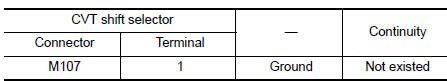
4.CHECK GROUND CIRCUIT
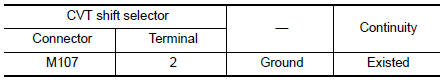
Check continuity between CVT shift selector harness connector terminal and ground.
Is the inspection result normal? YES >> GO TO 5.
NO >> Repair or replace malfunctioning parts.
5.CHECK CIRCUIT BETWEEN CVT SHIFT SELECTOR AND COMBINATION METER (PART 1)
- Turn ignition switch OFF.
- Disconnect combination meter connector.
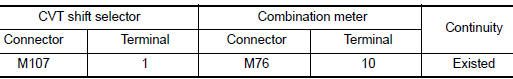
- Check continuity between CVT shift selector harness connector terminal and combination meter harness connector terminal.
the inspection result normal? YES >> GO TO 6.
NO >> Repair or replace malfunctioning parts.
6.CHECK CIRCUIT BETWEEN CVT SHIFT SELECTOR AND COMBINATION METER (PART 2)
Check continuity between CVT shift selector harness connector terminal and ground.
Is the inspection result normal? YES >> GO TO 7.
NO >> Repair or replace malfunctioning parts.
7.CHECK COMBINATION METER INPUT/OUTPUT SIGNAL
- Connect all of disconnected connectors.
- Turn ignition switch ON.
- Select “Data Monitor” in “METER/M&A”.
- Select “O/D OFF SW”.
- Check that “O/D OFF SW” turns ON/OFF when overdrive control switch is operated. Refer to MWI-24, "Reference Value".
Is the inspection result normal?
YES >> Check intermittent incident. Refer to GI-41, "Intermittent Incident".
NO >> Replace combination meter. Refer to MWI-82, "Removal and Installation".
Component Inspection
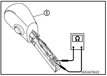
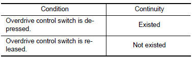
1.CHECK OVERDRIVE CONTROL SW
Check continuity between wires of shift selector knob 1.
Is the inspection result normal? YES >> INSPECTION END
NO >> Replace shift selector knob. Refer to TM-194, "Removal and Installation".
 Main power supply and ground circuit
Diagnosis Procedure
1.CHECK TCM POWER CIRCUIT (PART 1)
Turn ignition switch OFF.
Disconnect TCM connector.
Check voltage between TCM harness connector terminals and ground.
...
 O/D off indicator lamp
Component Function Check
1.CHECK O/D OFF INDICATOR LAMP FUNCTION
Check O/D OFF indicator lamp turns ON for approx. 2 seconds when ignition
switch turns ON.
Is the inspection results normal?
YE ...
Other materials:
P0453 EVAP control system pressure sensor
DTC Description
DTC DETECTION LOGIC
DTC No.
CONSULT screen terms
(Trouble diagnosis content)
DTC detecting condition
P0453
EVAP SYS PRES SEN
(Evaporative emission system pressure
sensor/switch high)
An excessively high voltage from the sensor is sent to ECM.
...
P2135 TP sensor
DTC Description
DTC DETECTION LOGIC
DTC No.
CONSULT screen terms
(Trouble diagnosis content)
DTC detecting condition
P2135
TP SENSOR-B1
(Throttle/pedal position sensor/switch ″A″ /
″B″ voltage correlation)
Rationally incorrect voltage is ...
FM/AM/SAT radio with compact disc (CD) player (Type A) (if so equipped)
FM/AM/SAT radio with compact disc (CD) player (Type A)
CD eject button
XM button*
Display screen
CD insert slot
SEEK button
SCAN button
CAT button
BACK button
APPS button
ENTER/SETTING button/ TUNE/SCROLL
knob
&n ...
