Nissan Rogue Service Manual: Main power supply and ground circuit
Diagnosis Procedure
1.CHECK TCM POWER CIRCUIT (PART 1)
- Turn ignition switch OFF.
- Disconnect TCM connector.
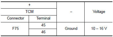
- Check voltage between TCM harness connector terminals and ground.
Is the inspection result normal? YES >> GO TO 2.
NO >> GO TO 4.
2.CHECK TCM POWER CIRCUIT (PART 2)
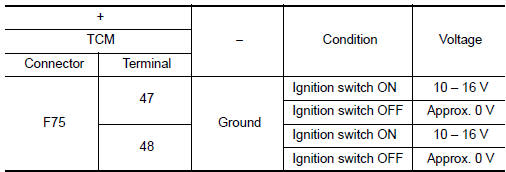
Check voltage between TCM harness connector terminals and ground.
Is the inspection result normal? YES >> GO TO 3.
NO >> GO TO 5.
3.CHECK TCM GROUND CIRCUIT
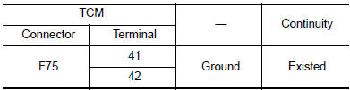
Check continuity between TCM harness connector terminals and ground.
Is the inspection result normal? YES >> Check intermittent incident. Refer to GI-41, "Intermittent Incident".
NO >> Repair or replace malfunctioning parts.
4.DETECT MALFUNCTION ITEMS (PART 1)
Check the following items:
- Open circuit or short circuit in harness between battery positive terminal and TCM connector terminal 45, and 46.
- 10A fuse (No.59, located in the fuse and fusible link block). Refer to PG-65, "Terminal Arrangement".
Is the inspection result normal? YES >> Check intermittent incident. Refer to GI-41, "Intermittent Incident".
NO >> Repair or replace malfunctioning parts.
5.CHECK CIRCUIT BETWEEN IPDM E/R AND TCM
- Turn ignition switch OFF.
- Disconnect IPDM E/R connector.
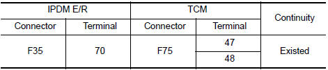
- Check continuity between IPDM E/R harness connector terminal and TCM harness connector terminals.
Is the check result normal? YES >> GO TO 6.
NO >> Repair or replace malfunctioning parts.
6.DETECT MALFUNCTIONING ITEMS (PART 2)
Check the following items:
- Open circuit or short circuit in harness between ignition switch and IPDM E/R. Refer to PG-15, "Wiring Diagram — Ignition Power Supply —".
- Short circuit in harness between IPDM E/R harness connector terminal 70 and TCM harness connector terminals 47, and 48.
- 10A fuse (No.46, located in the IPDM E/R). Refer to PG-68, "IPDM E/R Terminal Arrangement".
- IPDM E/R
Is the check result normal? YES >> Check intermittent incident. Refer to GI-41, "Intermittent Incident".
NO >> Repair or replace malfunctioning parts.
 P2815 select solenoid
DTC Description
DTC DETECTION LOGIC
DTC
CONSULT screen terms
(Trouble diagnosis content)
DTC detection condition
P2815
SELECT SOLENOID
(Select solenoid)
When all of ...
 Overdrive control switch
Component Function Check
1.CHECK O/D OFF INDICATOR LAMP FUNCTION
Check O/D OFF indicator lamp turns ON for approx. 2 seconds when ignition
switch turns ON.
Is the inspection results normal?
YE ...
Other materials:
System
CHARGING SYSTEM
CHARGING SYSTEM : System Description
The generator provides DC voltage to operate the vehicle's electrical system
and to keep the battery charged.
The voltage output is controlled by the IC regulator.
SYSTEM DIAGRAM
POWER GENERATION VOLTAGE VARIABLE CONTROL SYSTEM
P ...
Wiring diagram
SRS AIR BAG SYSTEM
Wiring Diagram
...
Fuel tank
FWD
FWD : Exploded View
Fuel filler cap
Grommet
Fuel filler tube
Cover
Clamp
Fuel filler hose
Clamp
Vent hose
Fuel tank protector
Fuel tank strap (LH)
Fuel tank strap (RH)
Fuel tank
T ...
