Nissan Rogue Service Manual: Oil pan and oil strainer
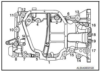
Exploded View
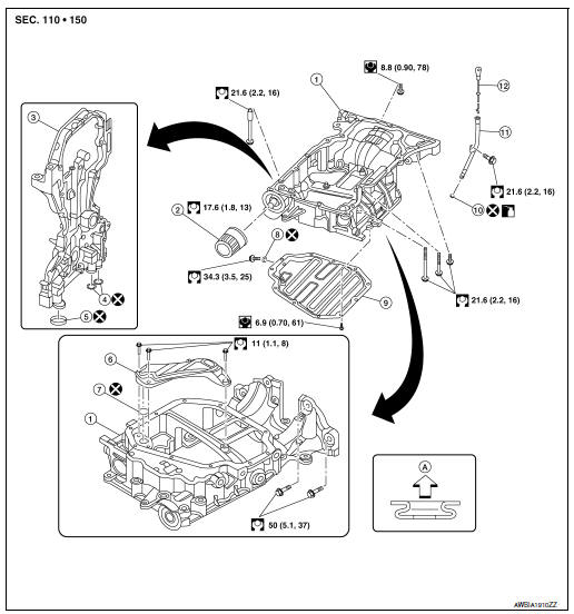
- Oil pan, upper
- Oil filter
- Front cover
- O-ring
- Oil strainer
- Oil pan, lower
- Washer
- Drain plug
- O-ring
- Oil level gauge guide
- Oil level gauge
- Rear cover plate
- To Oil pan, lower
Removal and Installation
REMOVAL
WARNING: To avoid danger of being scalded, do not drain engine oil when engine is hot.
- Drain engine oil. Refer to LU-8, "Draining".
- Remove the oil filter. Refer to LU-10, "Removal and Installation".
- Remove fender protector (RH). Refer to EXT-28, "FENDER PROTECTOR : Removal and Installation".
- Remove the front driveshaft (RH). Refer to FAX-20, "Removal and Installation (RH)".
- Remove the front exhaust tube and gaskets. Refer to EX-5, "Exploded View".
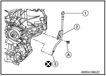
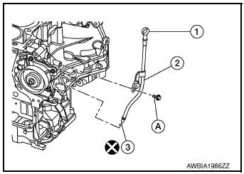
- Remove bolt (A) securing oil level gauge (2).
- Remove oil level gauge (1), oil level gauge guide (2), and O-ring (3).
- Remove the power steering gear bolts and support the power steering gear. Refer to ST-14, "Removal and Installation".
- Remove the rear engine mount torque rod bracket. Refer to EM-81, "Exploded View".
- . Remove the front suspension member for clearance to remove the oil pan. Refer to FSU-20, "Removal and Installation".
- On models equipped with AWD, remove transfer assembly. Refer to DLN-70, "Removal and Installation".
- Disconnect the A/C compressor harness connector.
- Remove the A/C compressor bolts, position the A/C compressor aside and support. Refer to HA-30, "Removal and Installation".
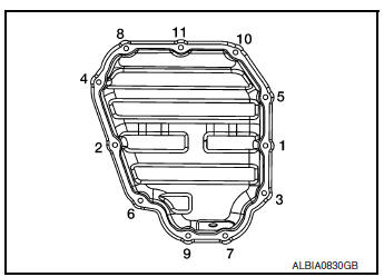
- Remove the lower oil pan bolts in the reverse order as shown.
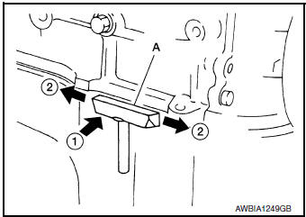
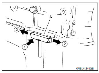
- Remove the lower oil pan using Tool (A).
CAUTION: Be careful not to damage the mating surfaces.
NOTE: In areas where the cutter is difficult to use, use a plastic hammer to lightly tap (1) the cutter where the liquid gasket is applied. Use a plastic hammer to slide (2) the cutter by tapping on the side.
Tool number : KV10111100 (J-37228)
- Remove the oil strainer bolts in the reverse order as shown then remove the oil strainer.
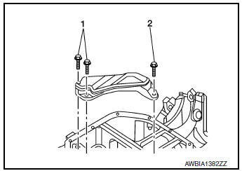
- Remove rear cover plate and engine-to transaxle bolts.
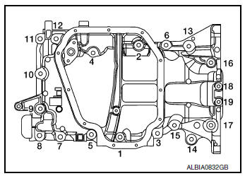
- Loosen the upper oil pan bolts in the order shown.
- Remove upper oil pan using Tool (A).
- Remove the three O-rings from the upper oil pan and front
cover.
CAUTION: Be careful not to damage the mating surfaces.
NOTE: In areas where the cutter is difficult to use, use a plastic hammer to lightly tap (1) the cutter where the liquid gasket is applied. Use a plastic hammer to slide (2) the cutter by tapping on the side.
Tool number : KV10111100 (J-37228)
INSPECTION AFTER REMOVAL
Clean the oil strainer screen to remove any foreign material.
INSTALLATION
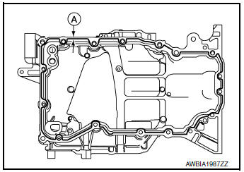
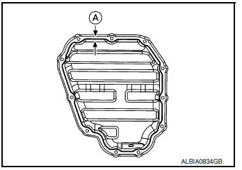
- Apply Genuine Silicone RTV Sealant or equivalent to the upper
oil pan at the specified sealant bead diameter (A) as shown.
Refer to GI-22, "Recommended Chemical Products and Sealants".
Sealant bead diameter (A) : 4.0 - 5.0 mm (0.157 - 0.197 in)
CAUTION:
- Be sure liquid gasket application surface is free from dust, grease, and water.
- Install two new O-rings in the upper oil pan and a new Oring in the front cover.
- Do not reuse O-rings.
- Be sure to apply liquid gasket to the outside of bolt holes 1, 2, and 4.
- Be sure to apply liquid gasket without breaks or overlap.
- Installation should be done within 5 minutes after applying liquid gasket.
- Do not fill the engine with engine oil for at least 30 minutes after the components are installed to allow the liquid gasket to cure.
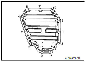
- Install the upper oil pan to the block and tighten the upper oil pan
bolts to specification in the order shown.
CAUTION: Install upper oil pan bolts in the same position from which they were removed.
All bolts except 18 and 19 : 21.6 N·m (2.2 kg-m, 16 ft-lb)
Bolts 18 and 19 : 8.8 N·m (0.90 kg-m, 78 in-lb)
- Apply Genuine Silicone RTV Sealant or equivalent to the lower
oil pan at the specified sealant bead diameter (A) as shown.
Refer to GI-22, "Recommended Chemical Products and Sealants".
CAUTION:
- Be sure liquid gasket application surface is free from dust, grease, and water.
- Be sure to apply liquid gasket to the inside of all bolt holes.
- Be sure to apply liquid gasket without breaks or overlap.
- Installation should be done within 5 minutes after applying liquid gasket.
- Do not fill the engine with engine oil for at least 30 minutes after the components are installed to allow the liquid gasket to cure.
Sealant bead diameter (A) : 4.0 - 5.0 mm (0.157 - 0.197 in)
- Install the lower oil pan to the upper oil pan and tighten the lower oil pan bolts to specification in the numerical order shown.
- Install oil level gauge (1), oil level gauge guide (2), and O-ring (3).
Bolt (A) : 21.6 N·m (2.2 kg-m, 16 ft-lb)
- Installation of the remaining components is in the reverse order of removal.
INSPECTION AFTER INSTALLATION
Check for engine oil leaks with the engine at operating temperature and running at idle. Refer to LU-7, "Inspection".
 Exhaust manifold and three way
catalyst
Exhaust manifold and three way
catalyst
Exploded View
Cylinder head
Exhaust manifold and three way
catalyst gasket
Exhaust manifold cover (upper)
Exhaust manifold and three way catalyst
Exhaust manifold ...
 Ignition coil
Exploded View
Ignition coil
Spark plug
Rocker cover
Removal and Installation
REMOVAL
Remove air duct assembly. Refer to EM-24, "Exploded View" .
Dis ...
Other materials:
Calibration of decel G sensor
Description
CAUTION:
Always perform the decel G sensor calibration before driving when the following
operation is performed.
NOTE:
Yaw rate/side/decel G sensor calibration is performed when performing the decel
G sensor calibration.
Work Procedure
Decel G sensor calibration
CAUTION: ...
Service data and specifications (SDS)
Wheel Alignment (Unladen*1)
*1: Fuel, engine coolant, and lubricants are full. Spare tire, jack, hand
tools, and mats are in designated positions.
*2: Since an adjustment mechanism is not included, the value of the left and
right wheels must be used as the standard value.
Wheelarch Height ...
Valve timing control
Exploded View
Valve timing cover
2. O-rings
Intake valve timing intermediate
lock control solenoid valve
Intake valve timing control solenoid
valve
Exhaust valve timing control solenoid
valve
Intake Valve Timing Intermediate Lock Control Solenoid Valve, Intake ...
